Fibrous structures comprising particles and methods for making same
a technology of fibrous structures and particles, applied in the field of fibrous structures, can solve the problems of consumers of fibrous structures wanting more and differen
- Summary
- Abstract
- Description
- Claims
- Application Information
AI Technical Summary
Benefits of technology
Problems solved by technology
Method used
Image
Examples
example 1
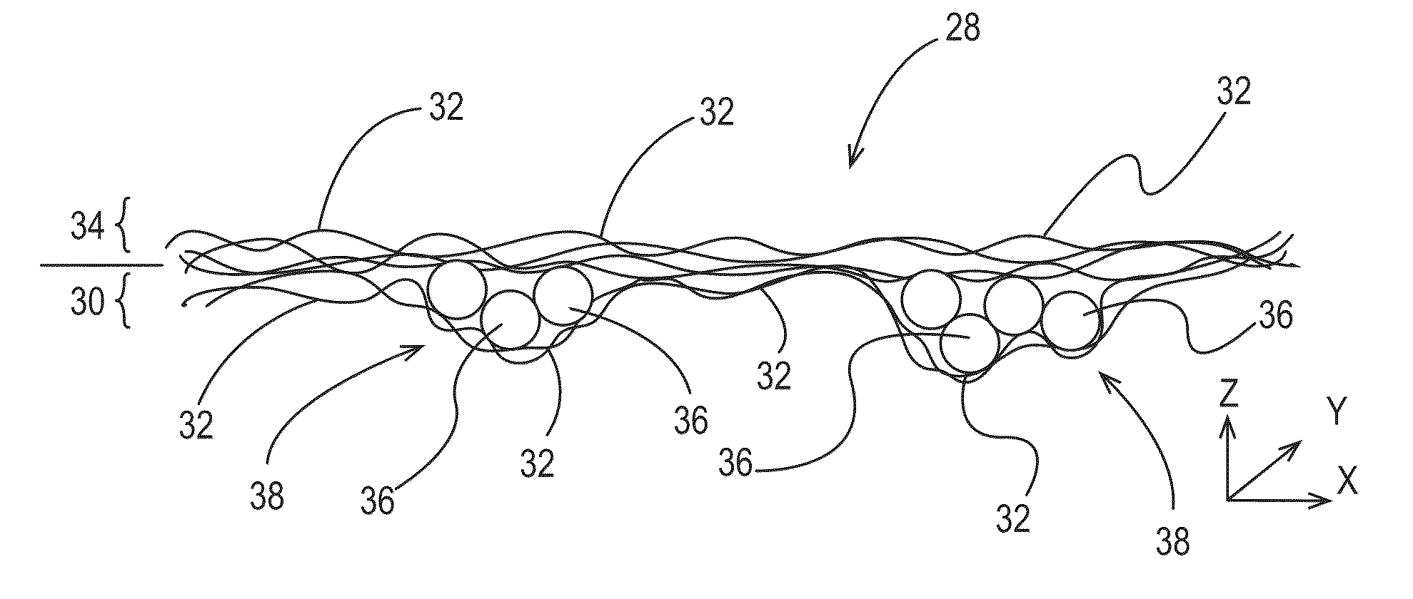
[0319]A first layer of fibrous elements is spun and collected on a patterned collection belt. The belt chosen for this example is shown in FIG. 14. The resulting first layer comprises pockets that extend in the z-direction of the first layer and ultimately the fibrous structure formed therefrom. The pockets are suitable for receiving particles. The first layer is left on the collection belt.
[0320]Table 1 below sets forth is an example of a filament-forming composition of the present invention, which is used to make the fibrous elements in these non-limiting examples. This filament-forming composition is made and placed in the pressurized tank 62 in FIG. 9.
TABLE 1% by weightof filament-Filament (i.e.,formingFilament-components% by weightcompositionFormingremainingon a dry(i.e., premix)Composition (%)upon drying) (%)filament basisC12-15 AES28.4511.3811.3828.07C11.8 HLAS12.224.894.8912.05MEA7.112.852.857.02N67HSAS4.511.811.814.45Glycerol3.081.231.233.04PE-20, Poly-3.001.201.202.95ethyl...
example 2
[0324]A particle source, for example a feeder, suitable to supply a flow of particles is placed directly above the drying region for the fibrous elements as shown in FIG. 11. In this case a vibratory feeder made by Retsch® of Haan, Germany, is used. In order to aid in a consistent distribution of particles in the cross direction the particles are fed onto a tray that started off the width of the feeder and ended at the same width as the spinning die face to ensure particles were delivered into all areas of fibrous element formation. The tray is completely enclosed with the exception of the exit to minimize disruption of the particle feed.
[0325]While embryonic fibrous elements are being formed, the feeder is turned on and particles are introduced into the fibrous element stream. In this case, Green Zero (Green Speckle Granules) manufactured by Genencor International® of Leiden, The Netherlands is used as the particles. The particles associated and / or mixed with the fibrous elements a...
example 3
[0326]The fibrous structure from Example 2 is used as a first layer for the fibrous structure of this Example. The first layer is passed under a spinning die twice such that both the top and bottom of the first layer was exposed to the fibrous elements being produced by the spinning die, thereby creating a tri-layered fibrous structure.
Automatic Dishwashing Articles
[0327]Automatic dishwashing articles comprise one or more fibrous structures of the present invention and a surfactant system, and optionally one or more optional ingredients known in the art of cleaning, for example useful in cleaning dishware in an automatic dishwashing machine. Examples of these optional ingredients include: anti-scalants, chelants, bleaching agents, perfumes, dyes, antibacterial agents, enzymes (e.g., protease, amylase), cleaning polymers (e.g., alkoxylated polyethyleneimine polymer), anti-redeposition polymers, hydrotropes, suds inhibitors, carboxylic acids, thickening agents, preservatives, disinfec...
PUM
| Property | Measurement | Unit |
|---|---|---|
| Diameter | aaaaa | aaaaa |
| Particle size | aaaaa | aaaaa |
| Particle size | aaaaa | aaaaa |
Abstract
Description
Claims
Application Information
 - R&D
- Intellectual Property
- Life Sciences
- Materials
- Tech Scout
- Unparalleled Data Quality
- Higher Quality Content
- 60% Fewer Hallucinations
Browse by: Latest US Patents, China's latest patents, Technical Efficacy Thesaurus, Application Domain, Technology Topic, Popular Technical Reports.
© 2025 PatSnap. All rights reserved.Legal|Privacy policy|Modern Slavery Act Transparency Statement|Sitemap|About US| Contact US: help@patsnap.com


