
Method of supercritical point drying with stasis mode

a drying method and critical point technology, applied in the direction of drying solid materials without heat, lighting and heating apparatus, and preliminary solid treatment, can solve the problems of destroying delicate structures, reducing liquid volume, and conventional drying is inappropriate for use on microelectromechanical systems (mems) devices, biological samples, etc., and achieves the effect of higher success ra

Inactive Publication Date: 2013-07-11
TOUSIMIS CHRIS
View PDF2 Cites 6 Cited by
  • Summary
  • Abstract
  • Description
  • Claims
  • Application Information

AI Technical Summary

Benefits of technology

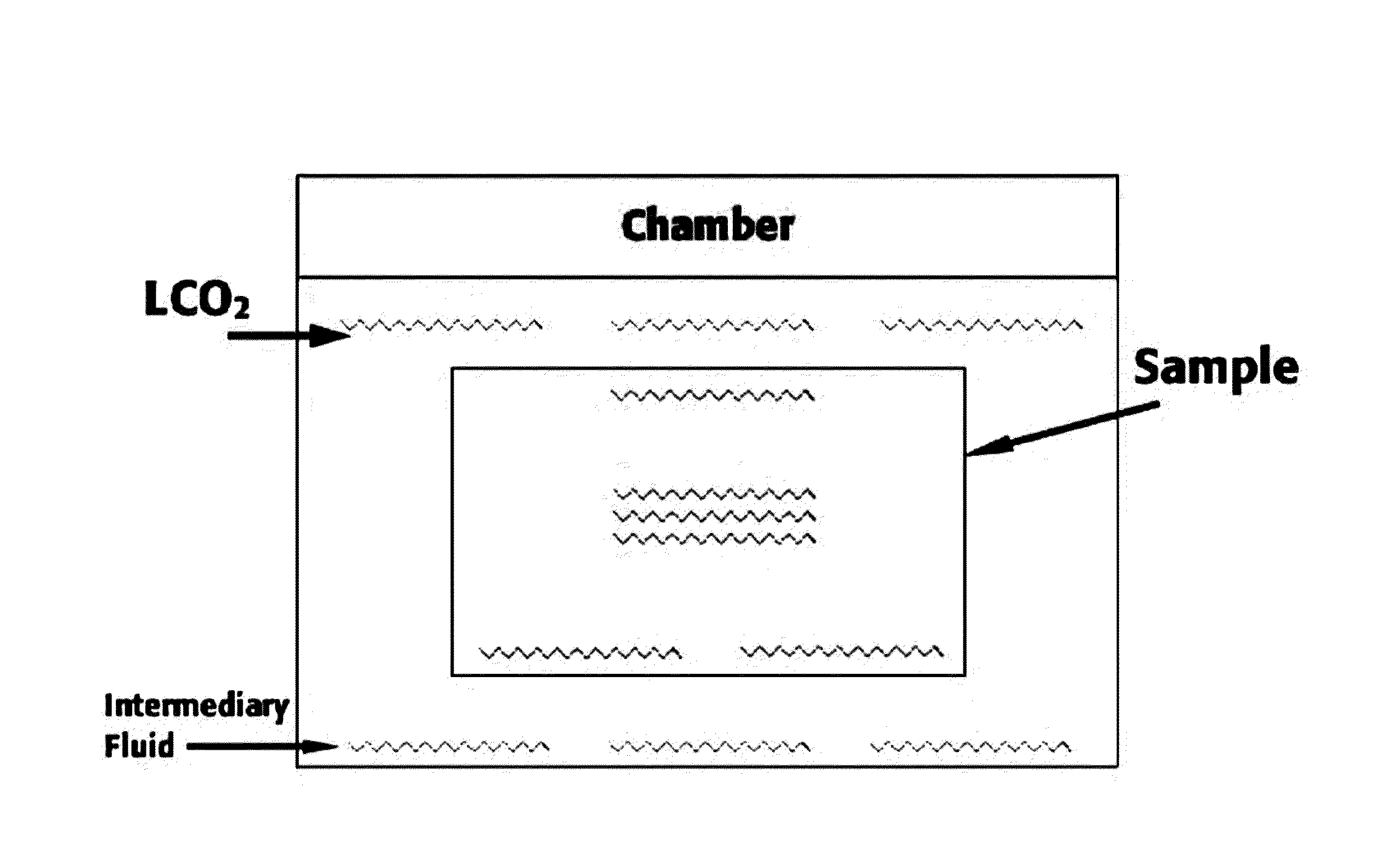
The invention is a method for drying samples using supercritical point drying. The method includes a "stasis mode" that allows for more thorough purging of the intermediary fluid from the sample and chamber, resulting in a higher success rate when drying thicker samples.

Problems solved by technology

During conventional drying processes a sample in a liquid state will change phases from liquid to gas, resulting in a decrease to the liquid volume.
This causes surface tension in the liquid which can destroy delicate structures.
Thus, conventional drying is inappropriate for use on some microelectromechanical systems (MEMS) devices, biological samples, or other delicate structures.
These boundary forces are what cause the destruction of the extremely delicate specimens when changing its internal liquid to a gas below the critical point.
Although the computer-controlled critical point drying apparatus substantially eliminates the need for constant operator attention, it has been found that thicker samples such as aerogels, sogels, MOF's (metal organic ferameworks) and hydrogels are not fully purged of transitional fluid during the purge step, resulting in a tainted sample.
The problem with the thicker samples is that the intermediary fluid, though purged from chamber 40, may still remain inside of the sample.
Thus, when the chamber 40 rises above the critical temperature and pressure, the sample structure will collapse due to the residual intermediary fluids still present inside of it, and an incomplete drying will occur.

Method used


Image

  • Method of supercritical point drying with stasis mode
  • Method of supercritical point drying with stasis mode
  • Method of supercritical point drying with stasis mode

Examples


Embodiment Construction

[0034]Reference will now be made in detail to preferred embodiments of the present invention, examples of which are illustrated in the accompanying drawings. Wherever possible, the same reference numbers will be used throughout the drawings to refer to the same or like parts.

[0035]The present invention is a method of supercritical point drying which includes a “stasis mode”, a specialized mode in which a state of inactivity is maintained for more thorough purging of the intermediary fluid from the sample and drying chamber, and ultimately a much higher success rate when drying thicker samples in the dryer.

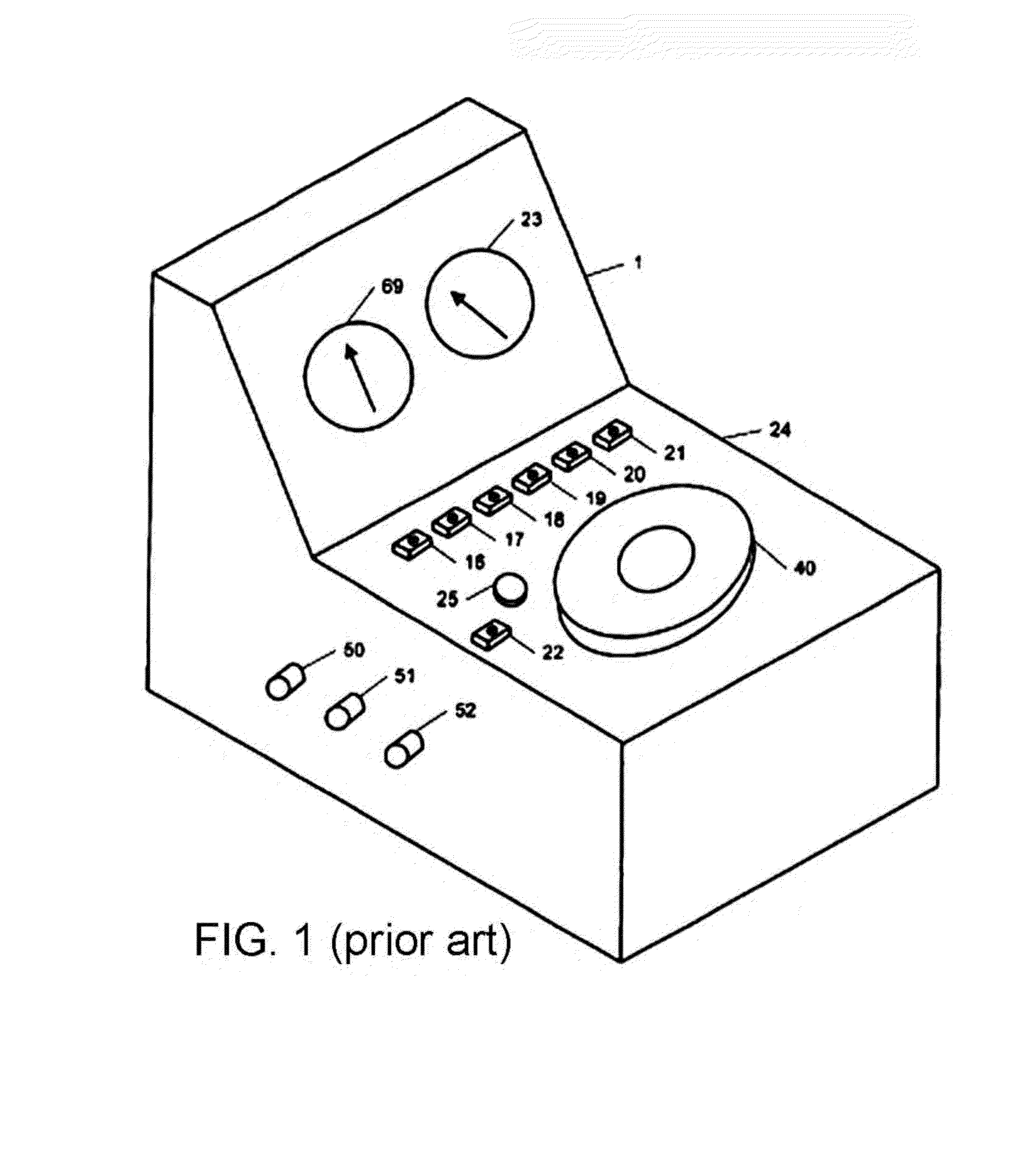
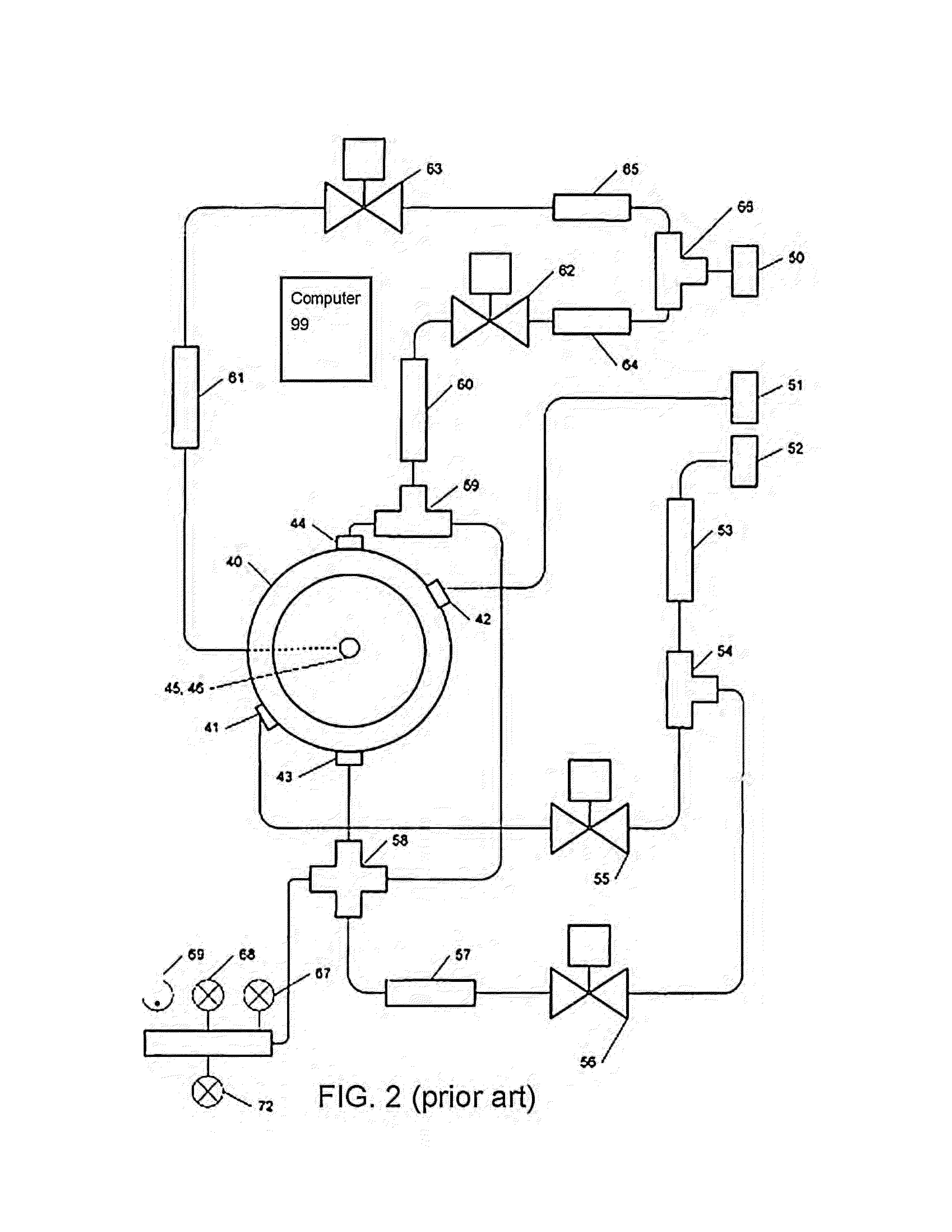
[0036]The present method may be implemented with a computer-controlled supercritical point drying apparatus as shown and described above with reference to FIGS. 1 and 2. As shown in FIG. 4, the computer system 99 includes a graphical user interface that allows the user to automatically complete the normal operational sequence for drying a sample in a dryer by pressing the Auto icon...


PUM


Abstract

An improved method for supercritical point drying of a treated sample immersed in an intermediate drying fluid (e.g., ethanol or acetone), by purging the intermediary fluid with transitional fluid, and then entering a “stasis mode” allowing the sample to sit in its liquid state in the transitional fluid for a predetermined amount of time to extract any residual intermediary fluid into the transitional fluid. This ensures more thorough purging of the intermediary fluid from the sample and drying chamber, ultimately yielding a much higher success rate when drying thicker samples in the dryer.

Description

CROSS-REFERENCE TO RELATED APPLICATION(S)[0001]The present application derives priority from U.S. provisional application Ser. No. 61 / 504,896 filed Jul. 6, 2011.BACKGROUND OF THE INVENTION[0002]1. Field of the Invention[0003]The present invention relates to improvements in critical point dryers for sample preparation for electron microscopy and semiconductor wafer manufacturing and, particularly, to a method for controlling a critical point drying apparatus using a computer system that employs a ‘stasis’ mode that effectively shuts down the apparatus and allows a sample to sit in a liquid state for a predetermined amount of time, so that any intermediary fluid in the sample can be fully purged.[0004]2. Description of the Background[0005]During conventional drying processes a sample in a liquid state will change phases from liquid to gas, resulting in a decrease to the liquid volume. This causes surface tension in the liquid which can destroy delicate structures. Thus, conventional d...

Claims


Application Information

Patent Timeline
Patent Type & Authority Applications(United States)
IPC IPC(8): F26B1/00
CPCF26B5/005H01L21/67028F26B1/00
Inventor TOUSIMIS, CHRIS
Owner TOUSIMIS CHRIS
Learn More