Acoustic separators

a technology of acoustic separator and separator plate, which is applied in the direction of mechanical vibration separation, separation process, manufacturing tools, etc., can solve the problems of not finding a solution to separate and manipulate different particles of similar sizes, operating in batch mode, and not in continuous flow

Inactive Publication Date: 2013-07-11
ISIS INNOVATION LTD
View PDF5 Cites 73 Cited by
  • Summary
  • Abstract
  • Description
  • Claims
  • Application Information

AI Technical Summary

Benefits of technology

[0022]In either of these methods, the parameter may be flow rate, such as volumetric flow rate, of the fluid through the separator, or fluid temperature, or fluid pressure, which will affect the flow of fluids in some cases. The parameter may be a dimension of the separation chamber, or of the inlet, or of the outlet, or any combination thereof. The parameter may be controlled by adjustment of the separator. In other cases the parameter may be controlled by constructing the separator to have the target dimension or dimensions. In other cases the parameter may be the frequency of the pressure waves. Any two or more of these parameters can be controllable
[0023]The modelling may include modelling of fluid flow through the separator, for example using the Navier-Stokes equation. The modelling may include modelling any one or more of: the acoustic force on the particles, the buoyancy of the particles, gravitational forces on the particles, and drag force exerted on the particles by the fluid.

Problems solved by technology

This presents the disadvantage that particles can only be separated on the basis of size and offers no solution to separating and manipulating different particles of similar sizes.
Centrifugation-based techniques (such as cell-saver devices in a biomedical context) offer a density-based alternative, but those devices usually require a minimum initial volume to operate and can only operate in batch mode, rather than in continuous flow.
Lipid particles, which are amongst the impurities the blood becomes contaminated with, can be particularly harmful to the patient.
Conventional membrane-based filtration of the lipids has shown some positive results, with the limitation that the filters used must have a pore size that is larger than the size of the blood components.
Centrifugation can be used to separate lipids, but it has to be carried out in batch and some of the blood can be lost during this off-line procedure.
The scale-up strategy through replication of the single channel unit is often reported as the most obvious one for microchannels; however, as the number of single microstructured channels increases, problems of flow distribution and lack of homogeneity of processing conditions between the various units are likely to emerge.

Method used


Image

  • Acoustic separators
  • Acoustic separators
  • Acoustic separators

Examples


Embodiment Construction

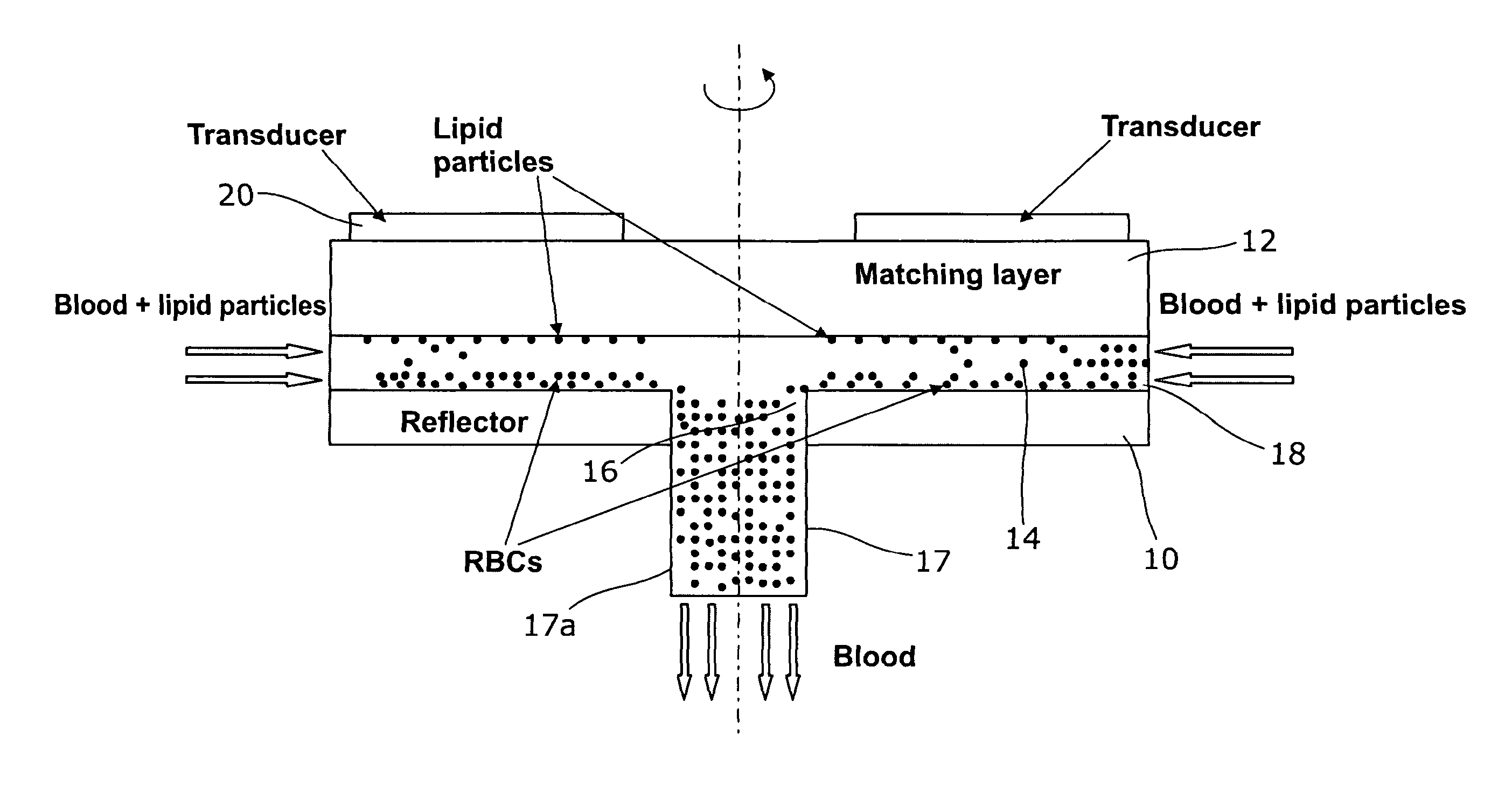
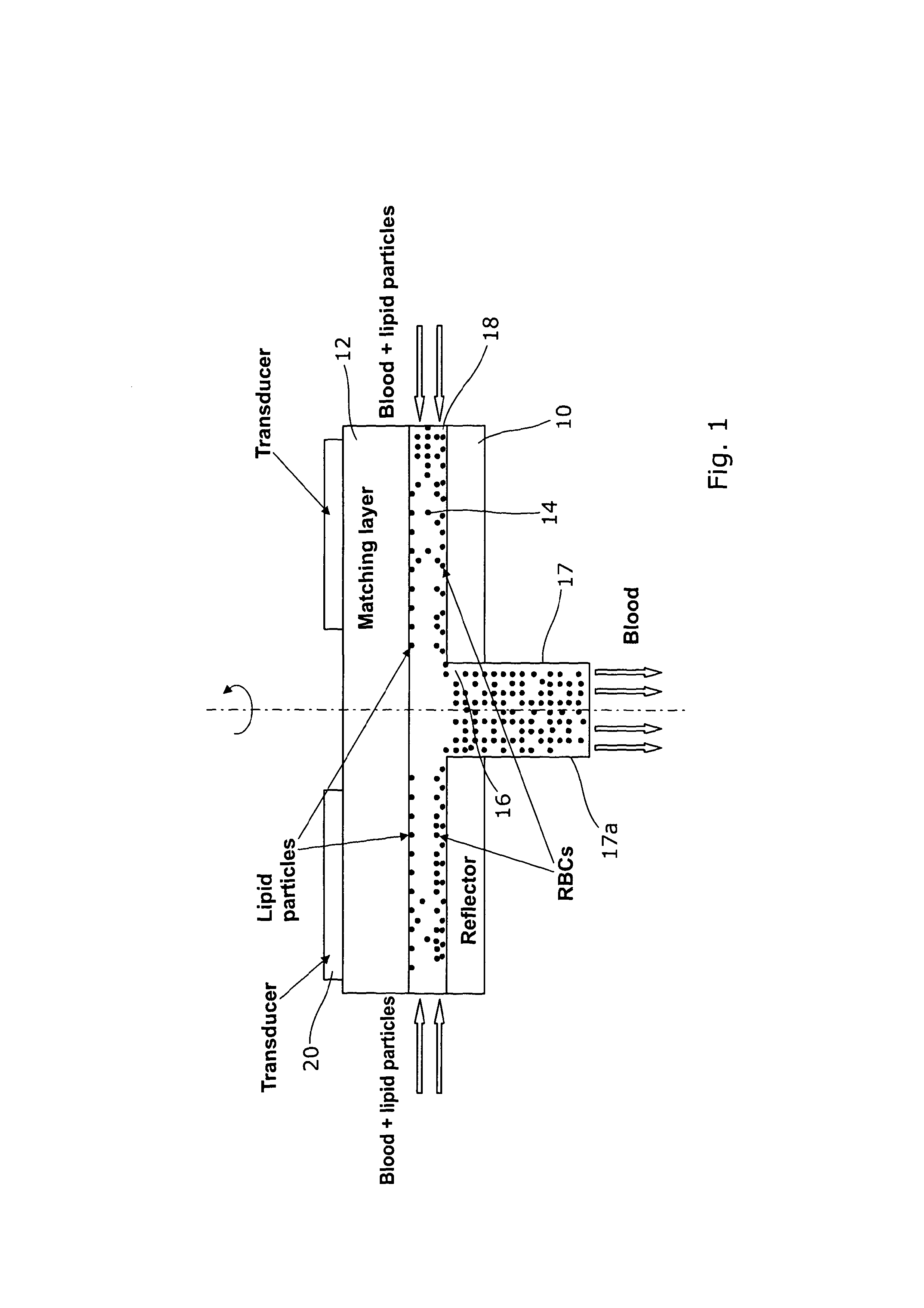
[0035]Referring to FIG. 1, an acoustic separator according to an embodiment of the invention comprises two parallel circular plates 10, 12 which form two side walls, defining a separation chamber 14 between them. The lower plate 10 has an aperture 16 in its centre which forms an outlet. An outlet duct 17 extends from the outlet 16 in the downward direction, perpendicular to the plates 10, 12. The side walls 17a of the outlet duct are joined to the lower plate 10 around the edge of the outlet 16 and extend downwards, perpendicular to the plates 10, 12. The radially outer edge of the separation chamber 14 forms an inlet 18 so that, in operation, fluid flows radially inwards from the edge of the separation chamber 14, and then turns through a right angle and flows axially outwards through the outlet 16. An annular piezoelectric transducer 20 is located on top of the upper plate 12 and is arranged to vibrate in the vertical direction transmitting acoustic waves vertically downwards thro...


PUM

PropertyMeasurementUnit
sizeaaaaaaaaaa
diameteraaaaaaaaaa
particle sizeaaaaaaaaaa

Abstract

An acoustic separator comprises: two parallel chamber walls defining a separation chamber therebetween, each chamber wall defining one side of the chamber; inlet means through which fluid can flow into the chamber; and outlet means through which fluid can flow out of the chamber. One of the chamber walls includes a transducer arranged to transmit pressure waves across the chamber towards the other of the chamber walls which in turn is arranged to reflect the pressure waves to set up a standing wave in the chamber. The outlet means defines an opening in one of the sides of the chamber.

Description

FIELD OF THE INVENTION[0001]The present invention relates to acoustic separators. It has application, for example, in the separation of micron-sized particles in a biomedical context, such as for the separation of lipid microemboli from pericardial suction blood (where it would replace cell-saver devices which are effectively centrifuges that can only be used in batch mode, rather than continuous flow). However, the invention can be scaled and adapted for a broad array of filtration and separation applications, such as in areas of chemical engineering such as handling or separation of emulsions and particle suspensions and in food processing.BACKGROUND OF THE INVENTION[0002]Particle separation is today most commonly achieved by conventional membrane filtration. This presents the disadvantage that particles can only be separated on the basis of size and offers no solution to separating and manipulating different particles of similar sizes. Centrifugation-based techniques (such as cel...

Claims


Application Information

Patent Timeline
Patent Type & Authority Applications(United States)
IPC IPC(8): B01D21/28
CPCA61M1/3633B01D21/283B01D2221/10Y10T29/49826A61M1/3693A61M1/3678A61M1/363B01D21/28
Inventor COUSSIOS, CONSTANTINVENTIKOS, YIANNISTRIPPA, GIULIANATAGGART, DAVID
Owner ISIS INNOVATION LTD
Why Eureka
Try Eureka