
System and method for plasma generation

Inactive Publication Date: 2013-07-11
PLASSEIN TECH LTD
View PDF4 Cites 5 Cited by
  • Summary
  • Abstract
  • Description
  • Claims
  • Application Information

AI Technical Summary

Benefits of technology

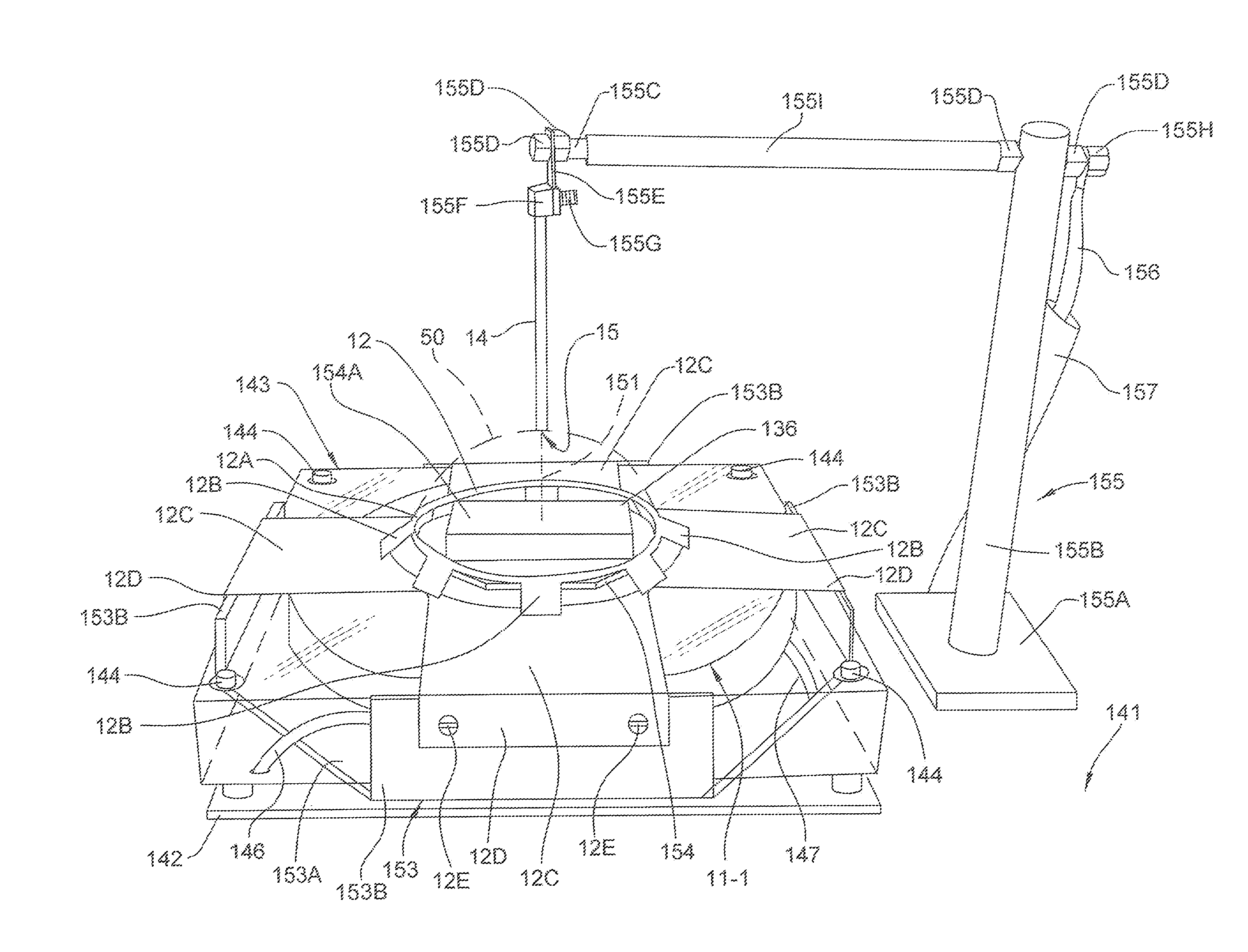
This patent is about a new device that creates a layer of plasma to protect objects or people from damage caused by impact or flames. The device has tubular or vertical electrodes that are designed to provide the best protection based on the needs of the user. One easily conceivable application is as a barrier to protect a ship from water borne flames. Another use is to provide a barrier against overpressure shock waves caused by chemical reactions. The device can be fixed or movable for use in different situations.

Problems solved by technology

However, while plasma is understood to be the most common form of matter in the universe, its use as a technology with widespread industrial applicability has been limited.
The use of plasmas in industry has traditionally been limited by various practical considerations.
Plasmas with energies that have been useful in industry typically have had volumes so large that they are cumbersome.
In addition, plasmas typically generate strong electromagnetic and RF interference, making plasma-based devices largely incompatible with other electronic devices.
Without the ability to control the interference generated by a plasma-based device, the operation of many electronic devices in the vicinity of the plasma-based device becomes needlessly compromised.

Method used


Image

  • System and method for plasma generation
  • System and method for plasma generation
  • System and method for plasma generation

Examples


Embodiment Construction

[0057]In the following description of preferred embodiments, reference is made to the accompanying drawings that form a part hereof, and in which is shown by way of illustration specific embodiments in which the invention may be practiced. It is to be understood that other embodiments may be utilized and structural changes may be made without departing from the scope of the preferred embodiments of the present invention.

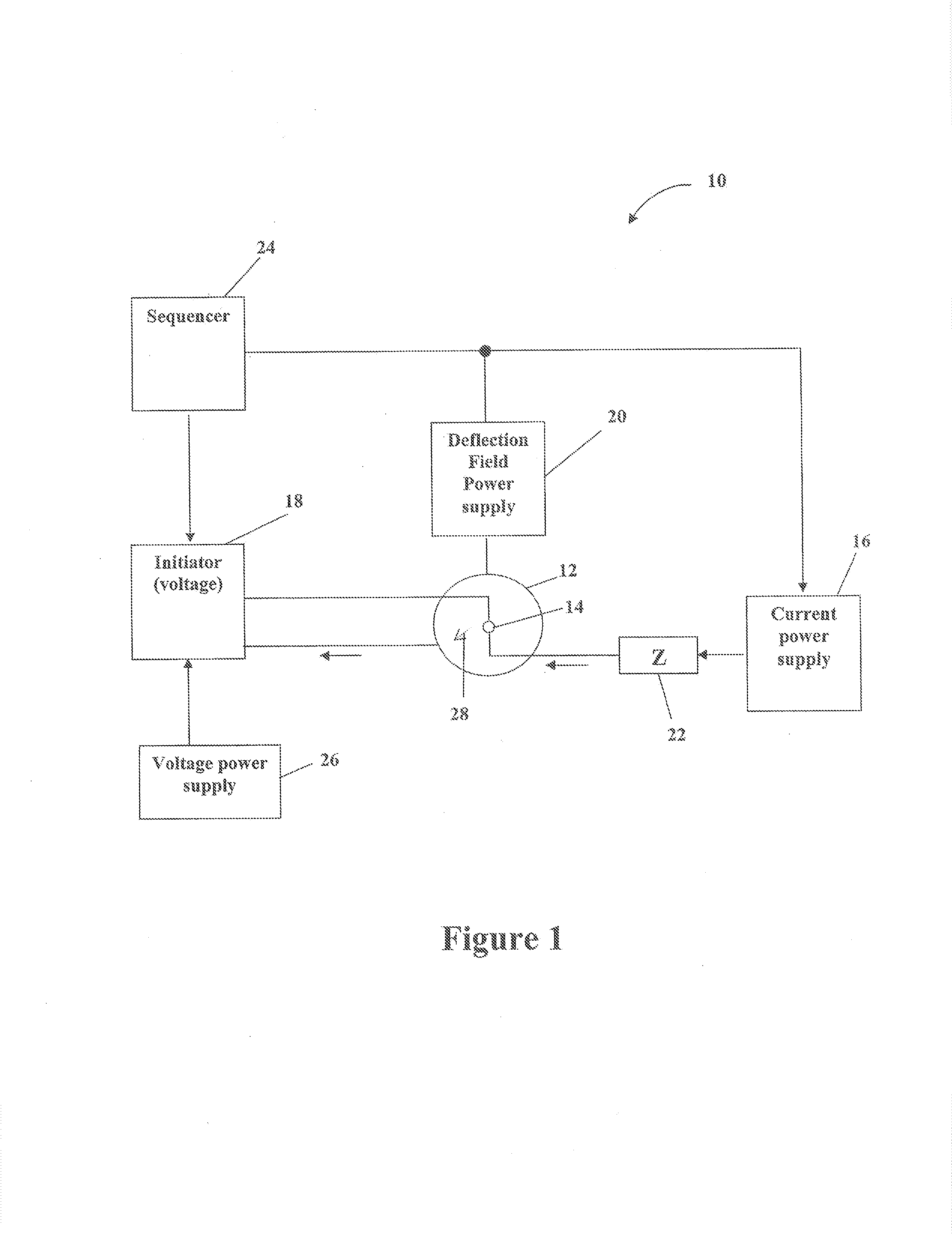
[0058]FIG. 1 shows a system for plasma generation 10 according to an embodiment of the present invention. The system 10 shown in FIG. 1 includes, but is not limited to, a first electrode 12, a second electrode 14, a deflection field power supply 20, a current power supply 16, an initiator supply 18 and a sequencer 24. The system 10 of FIG. 1 may also include a voltage power supply 26 and an impedance matching network 22.

[0059]In the embodiment of the invention shown in FIG. 1, the first electrode 12 and the second electrode 14 may be configured in a variety of ways. ...


PUM

PropertyMeasurementUnit
Poweraaaaaaaaaa
Magnetic fieldaaaaaaaaaa
Plasma poweraaaaaaaaaa

Abstract

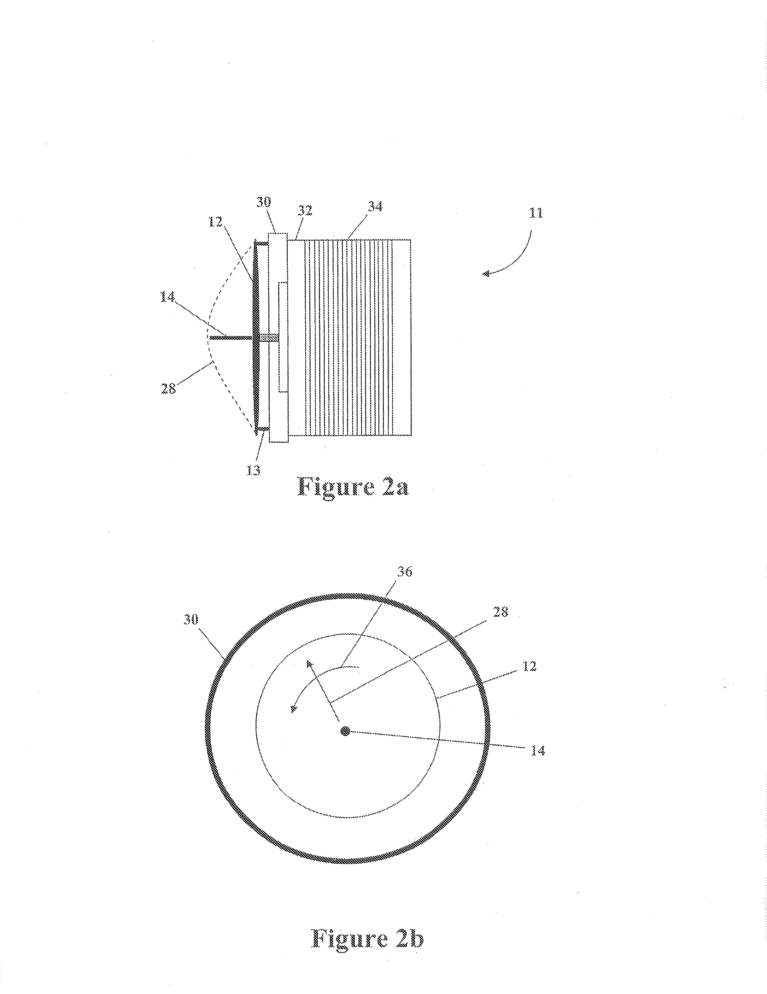
A system and method for generating a plasma. A first electrode and a second electrode are disposed adjacent to one another, not touching one another. A first power supply supplies power at the second electrode, and a second power supply generates a magnetic field. A sequencer coordinates a discharge of power from the first power supply and a discharge of power from the second power supply. The first power supply may be is configured such that the discharge of power from the first power supply generates a plasma between the first electrode and the second electrode. The second power supply is configured such that the magnetic field it generates rotates the plasma. Depending upon disclosed relative geometries of the electrodes and the magnetic field, the plasma is shaped alternatively as a disc, a dome, a sleeve, or a polygonal sheet.

Description

CROSS-REFERENCE TO RELATED APPLICATIONS[0001]This application is a continuation-in-part of U.S. Ser. No. 11 / 330,297, filed Jan. 11, 2006, now U.S. Pat. No. 8,253,057, which is a continuation-in-part of U.S. Ser. No. 10 / 934,154, filed Sep. 3, 2004, abandoned. This application is also a continuation-in-part of U.S. Ser. No. 13 / 596,026, filed Aug. 27, 2012, which is a continuation of U.S. Ser. No. 11 / 330,297, which is a continuation-in-part of U.S. Ser. No. 10 / 934,154. These priority applications are incorporated herein by reference, in their entireties, for all purposes.FIELD OF THE INVENTION[0002]Embodiments of the present invention relate to the field of plasma generation and, in particular, to the generation of plasma contained within a boundary without a container.BACKGROUND INFORMATION[0003]Plasmas have long been the subject of research and investigation and continue to be the focus of many academic and industrial studies. However, while plasma is understood to be the most common...

Claims


Application Information

Patent Timeline
IPC IPC(8): H05H1/16
CPCH05H1/16H05H2001/4682H05H1/46H05H2242/26
Inventor HUNT, JACKMAKI, MARK L.
Owner PLASSEIN TECH LTD
Learn More