Mobile terminal power receiving module utilizing wireless power transmission and mobile terminal rechargable battery including mobile terminal power receiving module

a mobile terminal and recharging battery technology, applied in the direction of transformers, inductances, transportation and packaging, etc., can solve the problems of excessive heat, reduced battery capacity, and increased heat radiation, so as to improve heat radiation, high power transmission efficiency, and sufficient capacity of mobile terminal recharging batteries

Inactive Publication Date: 2013-07-11
NITTO DENKO CORP
View PDF13 Cites 66 Cited by
  • Summary
  • Abstract
  • Description
  • Claims
  • Application Information

AI Technical Summary

Benefits of technology

[0029]This arrangement makes it possible to provide a mobile terminal rechargeable battery having a thin-film-shaped mobile terminal power receiving module. Because the mobile terminal power receiving module is formed to be thin, the capacity of the mobile terminal rechargeable battery is sufficiently large.
[0030]I

Problems solved by technology

This is disadvantageous in that the capacity of the battery must be reduced.
Moreover, because such high-power and highly-efficient wirele

Method used


Image

  • Mobile terminal power receiving module utilizing wireless power transmission and mobile terminal rechargable battery including mobile terminal power receiving module
  • Mobile terminal power receiving module utilizing wireless power transmission and mobile terminal rechargable battery including mobile terminal power receiving module
  • Mobile terminal power receiving module utilizing wireless power transmission and mobile terminal rechargable battery including mobile terminal power receiving module

Examples


first embodiment

[0041]A mobile terminal power receiving module 1 according to First Embodiment will be described with reference to figures.

[0042](Outline of Mobile Terminal Power Receiving Module 1)

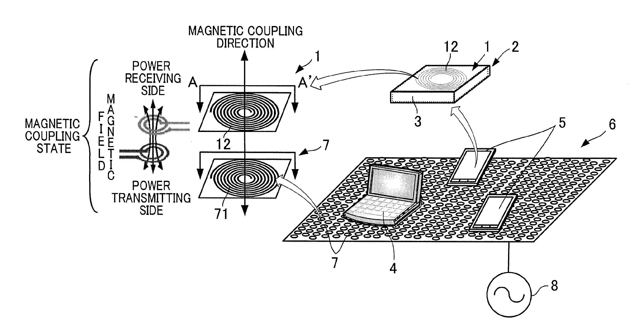
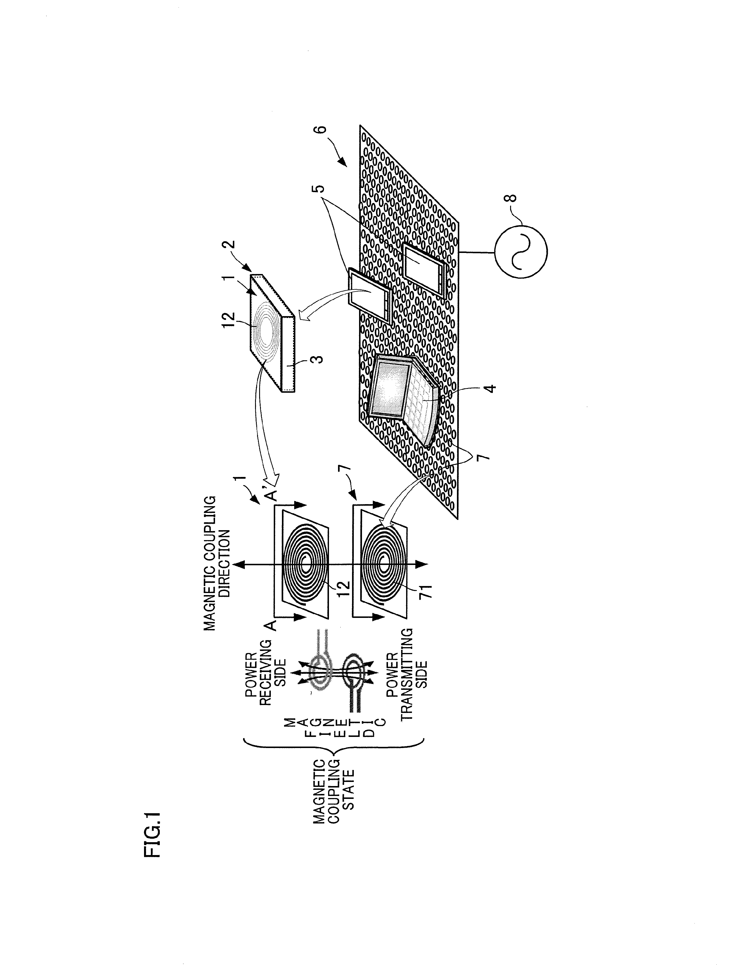
[0043]As shown in FIG. 1, the mobile terminal power receiving module 1 is used in the state of being housed, along with a rechargeable battery 3, in a rechargeable battery pack 2 of a note PC 4 or a smart phone 5. The mobile terminal power receiving module 1 is paired with a plurality of power transmitting modules 7 embedded in a power transmission sheet 6, and an induced electromotive force is generated by magnetic coupling between the mobile terminal power receiving module 1 and the power transmitting modules 7. With this, the mobile terminal power receiving module 1 is able to receive electric power from the power transmitting modules 7 in a wireless manner. The rechargeable battery 3 is charged with the received electric power. In addition to the above, the mobile terminal power receiving module 1 ma...

second embodiment

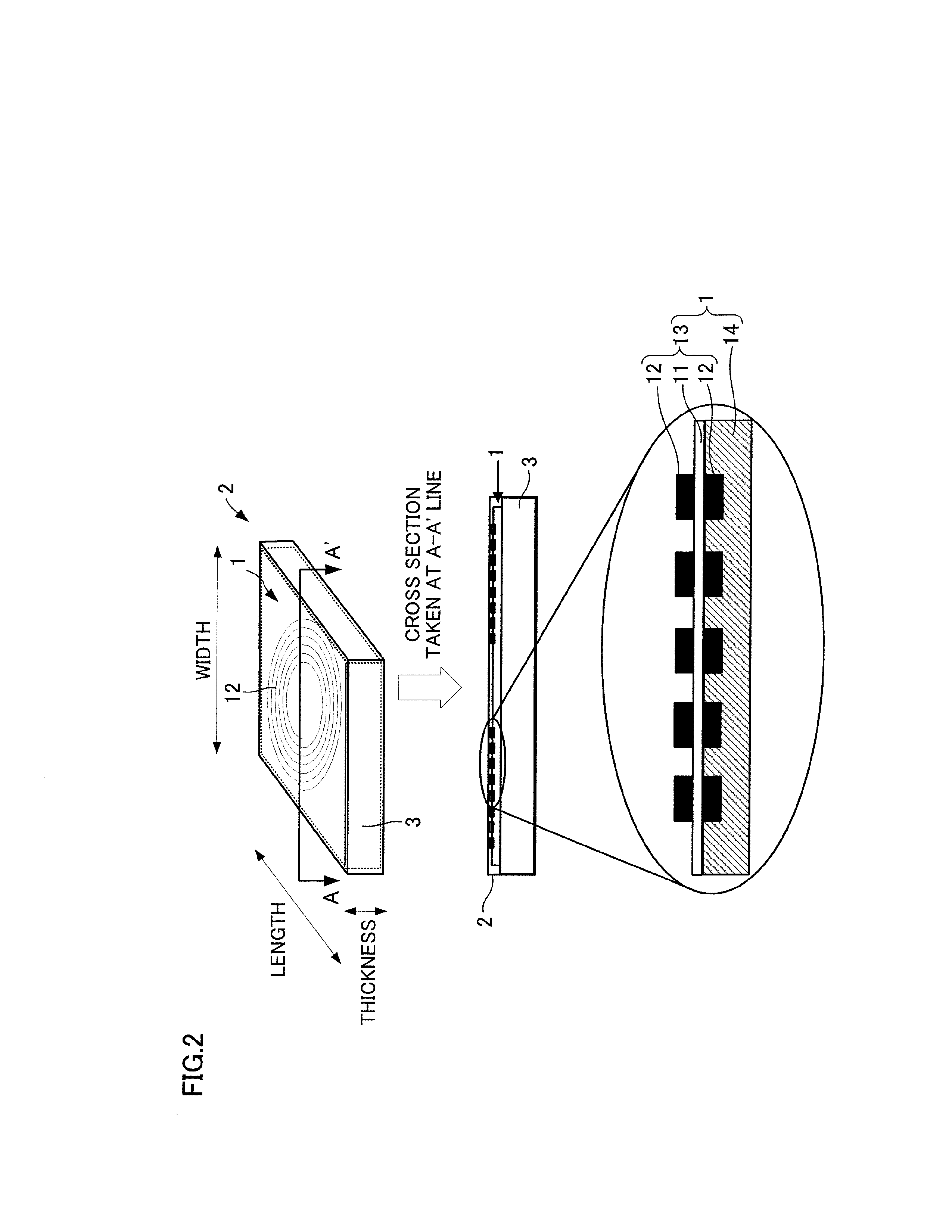
[0100]While the mobile terminal power receiving module 1 of First Embodiment is arranged so that the coils 12 are formed on the top and bottom surfaces of the flexible circuit board 11 to secure a sufficient number of spiral arms of the coils 12, the coil 12 may be provided only on the top surface of the flexible circuit board 11 as shown in FIG. 5. In this case, the cost down and the simplification of the manufacturing process are achieved because it is unnecessary to process the bottom surface of the flexible circuit board 11.

third embodiment

[0101]While the mobile terminal power receiving module 1 of First Embodiment is arranged so that the coils 12 are formed on the top and bottom surfaces of the flexible circuit board 11 and the magnetic sheet 14 fills the gaps B between the conductors of the coil 12 on the bottom surface of the flexible circuit board 11, as shown in FIG. 6, the magnetic sheet 14 may be pasted onto the sheet coil 13 without filling the gaps B between the conductors of the coil 12 on the bottom surface of the flexible circuit board 11.


PUM


Abstract

A mobile terminal power receiving module 1 which is housed together with a rechargeable battery 3 in a rechargeable battery pack 2 in a mobile terminal such as a smart phone 5, includes a sheet coil 13 in which a coil 12 constituted by conductors is formed on a flexible circuit board 11 as a circuit pattern and a magnetic sheet 14 made of resin in which magnetic powder is dispersed.

Description

CROSS REFERENCE TO RELATED APPLICATION[0001]The present application claims priority from Japanese Patent Application No. 2012-000553, which was filed on Jan. 5, 2012, the disclosure of which is herein incorporated by reference in its entirety.BACKGROUND OF THE INVENTION[0002]The present invention relates to a mobile terminal power receiving module implementing a wireless power transmission method of non-contact power transmission and a mobile terminal rechargeable battery having the mobile terminal power receiving module.[0003]Hand-held mobile terminals such as note PCs, tablet PCs, digital cameras, and mobile phones (in particular smart phones) have rapidly become popular. Most of such mobile terminals are equipped with rechargeable batteries, and require periodic charging. To simplify the operation to charge the rechargeable battery of each mobile terminal, a growing number of devices charge the rechargeable battery by means of cordless power supply (wireless power transmission) u...

Claims


Application Information

Patent Timeline
IPC IPC(8): H02J7/00H01F38/14H01F17/00
CPCH04B5/0037H01F27/255H01F27/327H02J7/0042H04B5/0075H01F38/14H02J5/005H02J50/402H02J50/12H02J50/70H02J50/40H02J50/80H02J2310/22
Inventor YAMAZAKI, HIROSHIKAMEYAMA, KOJIROTOYODA, EIJISUNAHARA, HAJIME
Owner NITTO DENKO CORP
Why Eureka
Try Eureka