Magnetic Resonance Imaging Methods

a magnetic resonance and imaging method technology, applied in the field of nmr imaging methods, can solve the problems of magnetic fields and limit the sample appropriate for analysis

Active Publication Date: 2013-07-11
SCHLUMBERGER TECH CORP
View PDF14 Cites 7 Cited by
  • Summary
  • Abstract
  • Description
  • Claims
  • Application Information

AI Technical Summary

Benefits of technology

[0017]According to one aspect, a method is provided for performing NMR imaging on rocks that reliably provides indications of NMR properties, such as T2 distribution.
[0018]In another aspect methods are provided for conducting NMR imaging in a manner that permits resolving short T2 components (e.g., T2<3 milliseconds).
[0019]In one embodiment magnetic resonance imaging (MRI) of an object is conducted according to the following steps: (1) generating with NMR apparatus a field gradient along the object in a set direction, (2) obtaining a series of one-dimensional profiles (projections) of the object by subjecting the object under the field gradient to a series of RF pulse sequences, each sequence including an excitation pulse and refocusing pulses and recording the resulting echo train signals, each one-dimensional projection corresponding to a particular echo; (3) rotating t

Problems solved by technology

“Lengthy” echo times (on the order of several milliseconds) also pose the problem that in order to obtain a sufficient signal to noise ratio (SNR) required to resolve each of the image

Method used


Image

  • Magnetic Resonance Imaging Methods
  • Magnetic Resonance Imaging Methods
  • Magnetic Resonance Imaging Methods

Examples


Embodiment Construction

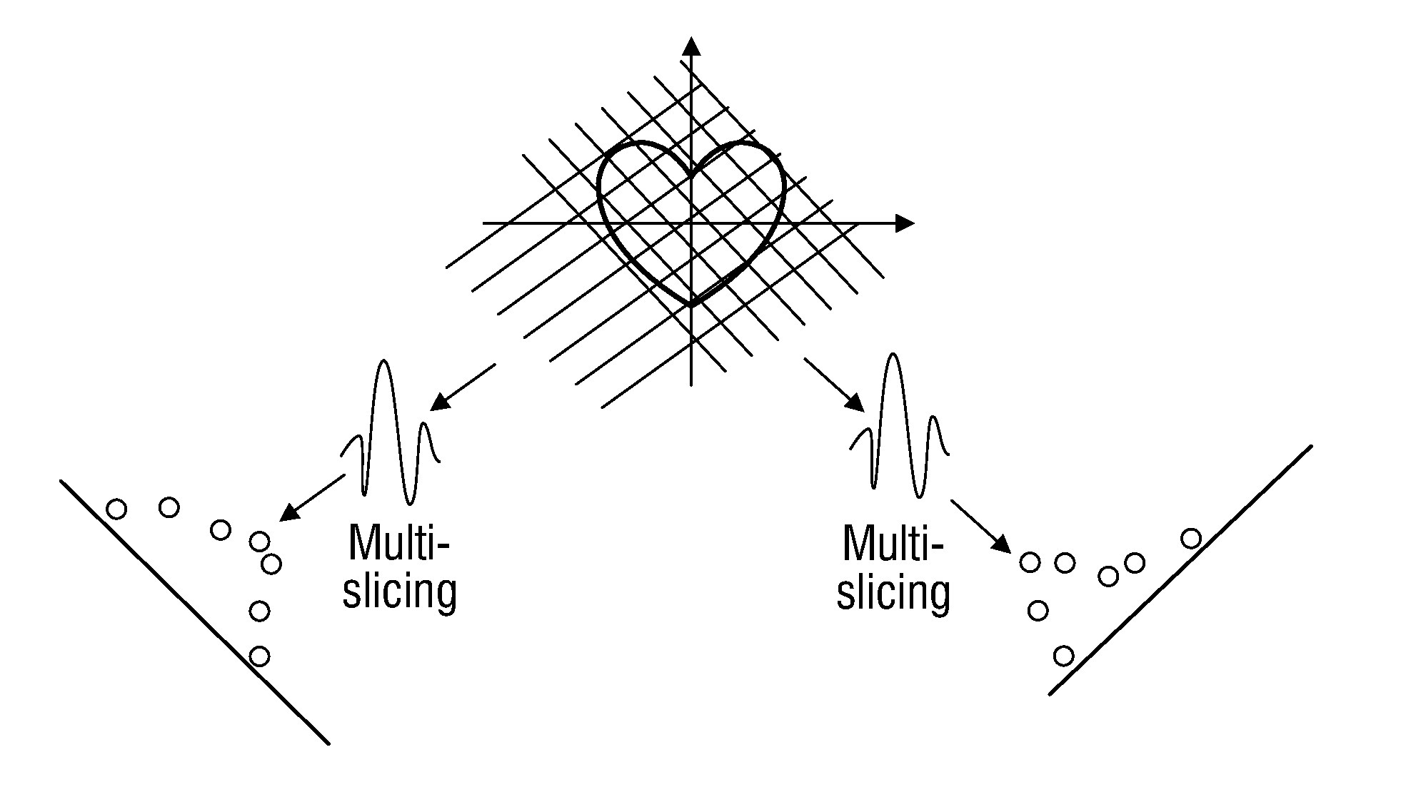
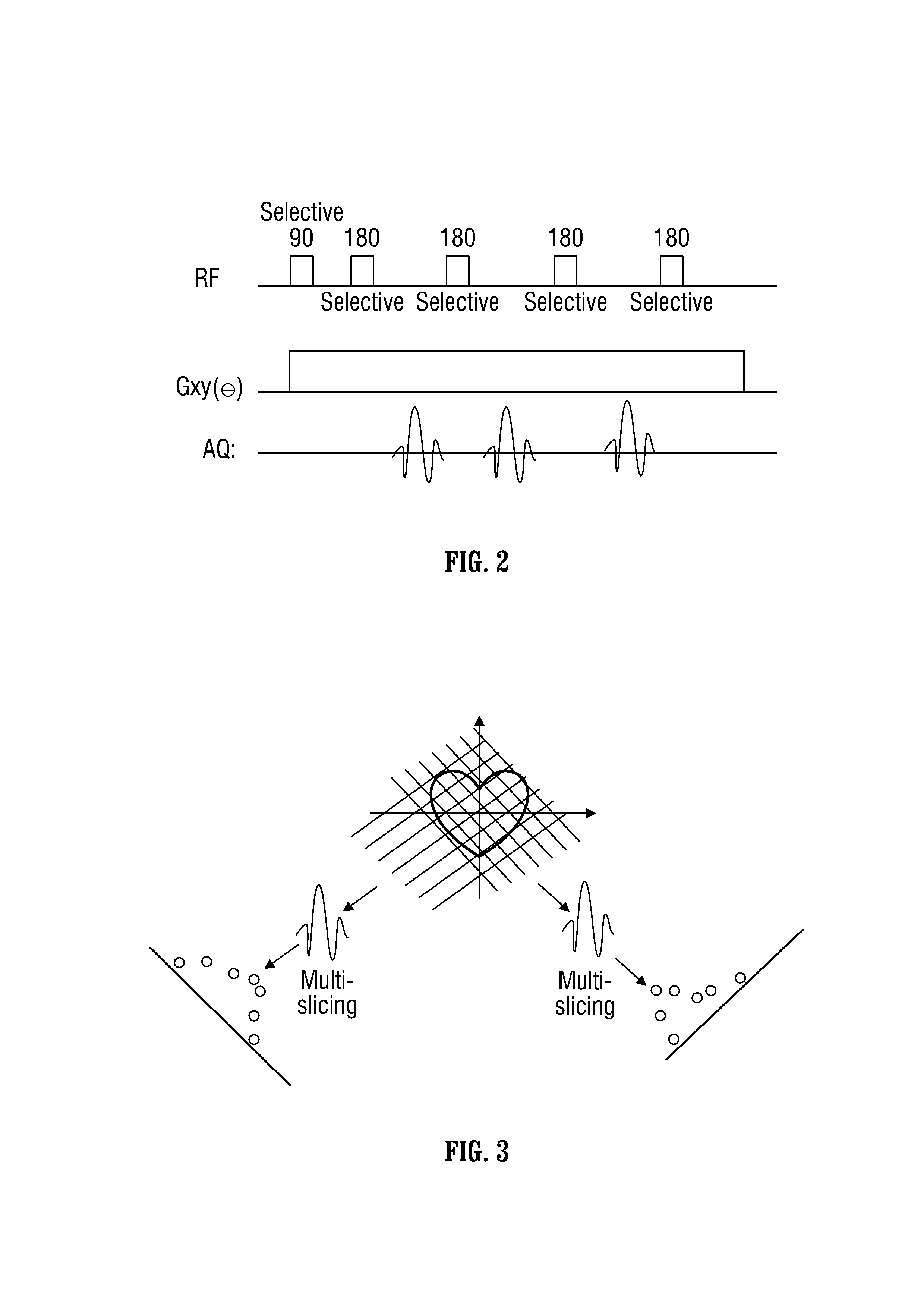
[0037]A flow diagram of one embodiment of an imaging method is seen in FIG. 1. More particularly, an object is investigated using an NMR apparatus (not shown), where a field gradient Gxy( ) is generated by the NMR apparatus at 12 along a set (first) direction. At 14, the RF pulse frequency is set to a set (first) frequency. At 15, a CPMG pulse sequence is generated, and echo train signals are acquired and stored by the NMR apparatus as discussed below with reference to FIG. 2. At 16, a determination is made as to whether echo train signals have been acquired for a desired number of different RF frequencies. If not, the RF frequency is changed to a new set frequency at 18 thereby changing the object slice position as discussed below with reference to FIG. 3, and the method returns to 15 where a CPMG pulse sequence is generated with the new RF frequency and echo train signals are acquired and stored. Steps 15, 16, and 18 are repeated until a determination is made at 16 that signals re...


PUM


Abstract

A method of investigating an object using nuclear magnetic resonance (NMR) equipment includes generating a one-dimensional projection of the object for each of a plurality of echoes utilizing echo train signal indications resulting from pulse sequences, and utilizing the plurality of one-dimensional projections, for each of the plurality of echoes, generating NMR image data for at least one location in the object. The NMR image data may be displayed. The displayed data may include a T2 decay curve, a T2 value display, a T2 distribution graph, or petrophysical data for at least one object location.

Description

CROSS-REFERENCE TO RELATED APPLICATION[0001]This application claims priority from U.S. Provisional Application 61 / 585,507, filed Jan. 11, 2012.BACKGROUND[0002]1. Field[0003]This case relates to nuclear magnetic resonance (NMR) imaging methods. More particularly, this case relates to NMR imaging methods that provide, among other things, an ability to resolve short “T2” components. This case has applicability to the imaging of rocks, including rocks previously or presently bearing hydrocarbons, although it is not limited thereto.[0004]2. Description of Related Art[0005]Nuclear magnetic resonance (NMR) involves the application of a magnetic field to an object that impacts the magnetic moment (spin) of an atom in the object. In general, the magnetic field causes the atoms in the object to align along and oscillate (precess) about the axis of the applied magnetic field. The spin of the atoms can be measured. Of particular interest is the return to equilibrium of this magnetization; i.e.,...

Claims


Application Information

Patent Timeline
IPC IPC(8): G01R33/54
CPCG01N24/081G01R33/4824G01R33/543G01R33/5617G01R33/50
Inventor SONG, YI-QIAOHAN, FEIPAULSEN, JEFFREY
Owner SCHLUMBERGER TECH CORP
Why Eureka
Try Eureka