Intra-ocular lens optimizer

a technology of optimizing lenses and ocular lenses, applied in the field of intraocular lens optimizing, can solve the problems of patients' functional blindness, patients' eyes appearing abnormally large to others, and affecting vision, and achieve the effect of minimal visual side effects and optimal eyesigh

Inactive Publication Date: 2013-07-11
DIGITALVISION
View PDF2 Cites 4 Cited by
  • Summary
  • Abstract
  • Description
  • Claims
  • Application Information

AI Technical Summary

Benefits of technology

[0043]In the wavefront generator, a projector, preferentially a digital display, projects a real image through optical elements that are under control of a computer. A focusing system, preferentially a spherical field mirror, focuses the wavefront generator to a position that is optically conjugate to the patient's eye. The focusing system may provide a near-viewing display accessory that can be placed at variable distances from the patient for near and intermediate viewing conditions and an eye tracker to stabilize the positions of the projected images.
[0045]The disclosure teaches the ability to test the tolerance of prospective implant patients to different IOL designs over a range of different distances and viewing conditions under monocular or binocular conditions. This permits IOL emulation under natural conditions, void of obstructing instruments, and it allows the patient to preview, compare, and select the IOL design, from a plurality of designs, that provides optimal eyesight with minimal visual side effects.

Problems solved by technology

A cataract is a clouding of the eye's clear crystalline lens that impairs vision.
These “aphakic spectacles” caused distortion of objects and caused the patient's eyes to appear abnormally large to others.
However, without their thick aphakic spectacles, these patients were functionally blind.
Diffractive IOLs have predictable near add power, but they scatter approximately 20% of the light and degrade image quality to a degree that some patients find unacceptable.
Accommodative lenses may not always couple to the delicate intraocular structures and move in the way their designers intended.
Despite the potential for presbyopia correcting IOLs to free post-cataract surgery patients from the need to wear corrective eyewear after surgery, there are major unsolved problems with prior art methods for selecting appropriate candidates for PC-IOL surgery, for identifying patients who will be dissatisfied with their implant, for determining which lens design will work best for a given patient, and for improving the designs of PC-IOLs.
There are presently limited and ineffective tools available to demonstrate to the patient the benefit that a presbyopia correcting IOL will provide in comparison to the vision that a monofocal IOL provides.
Thus, patients are presently asked to pay a considerable fee for a benefit that cannot be realistically demonstrated to them before surgery.
As more and more presbyopia correcting IOLs become available, ophthalmologists and their patients are exposed to an expanding number of choices and marketing claims that are difficult to evaluate objectively.
Unlike the shopper who may try on a new shoe to assess its fit and comfort before purchase, patients cannot presently preview and compare the vision that will be provided by different IOL designs prior to their cataract-IOL surgery.
Clinical experience with PC-IOLs has demonstrated that not all patients are good candidates for these lenses.
A lens exchange procedure subjects the patient to the additional risks and costs of surgery.
It has been reported that patients who are highly detail-oriented and / or who have demanding personalities are poor candidates for PC-IOL surgery, yet there are no commonly accepted objective standards for making such an assessment.
Yet, other surgeons dissuade such a strategy.
The prior art method of simulating a multifocal lens does not provide the patient a realistic assessment of the quality of vision that the multi-focal IOL will provide, because no means are provided to view objects of varying size, shape, color, contrast, and illumination; nor does the aforementioned patent application teach a means to view objects at near, intermediate, and far away distances.
Prior art devices provide no clinically practical method for determining which, if any, of the available designs of presbyopia correcting IOLs will provide a given patient with a satisfactory level of visual function following implantation of an intraocular lens, nor do they permit the patient to preview, compare, and select the IOL design that they prefer based upon a comparison of the IOLs image producing properties.

Method used


Image

  • Intra-ocular lens optimizer
  • Intra-ocular lens optimizer
  • Intra-ocular lens optimizer

Examples


Embodiment Construction

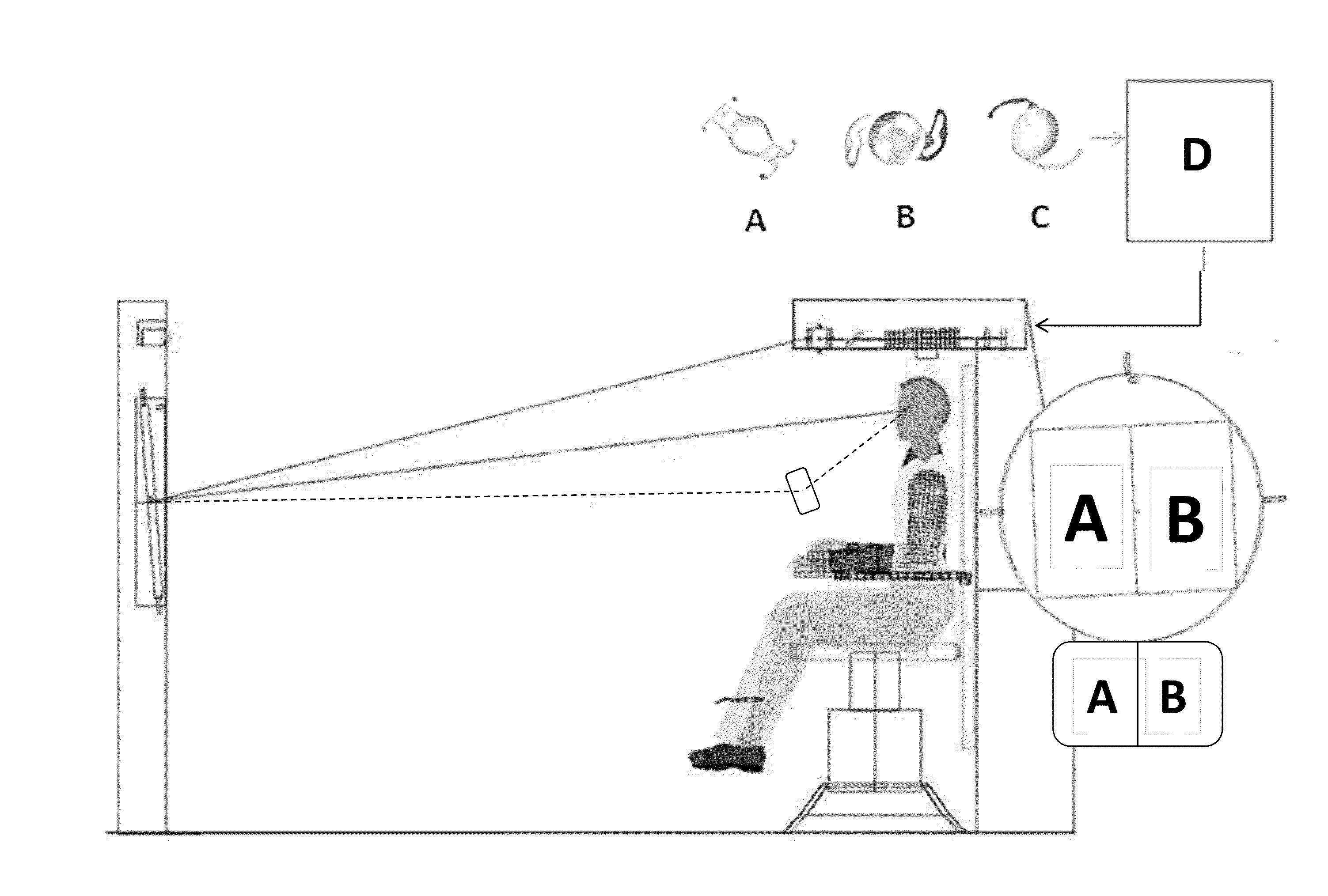
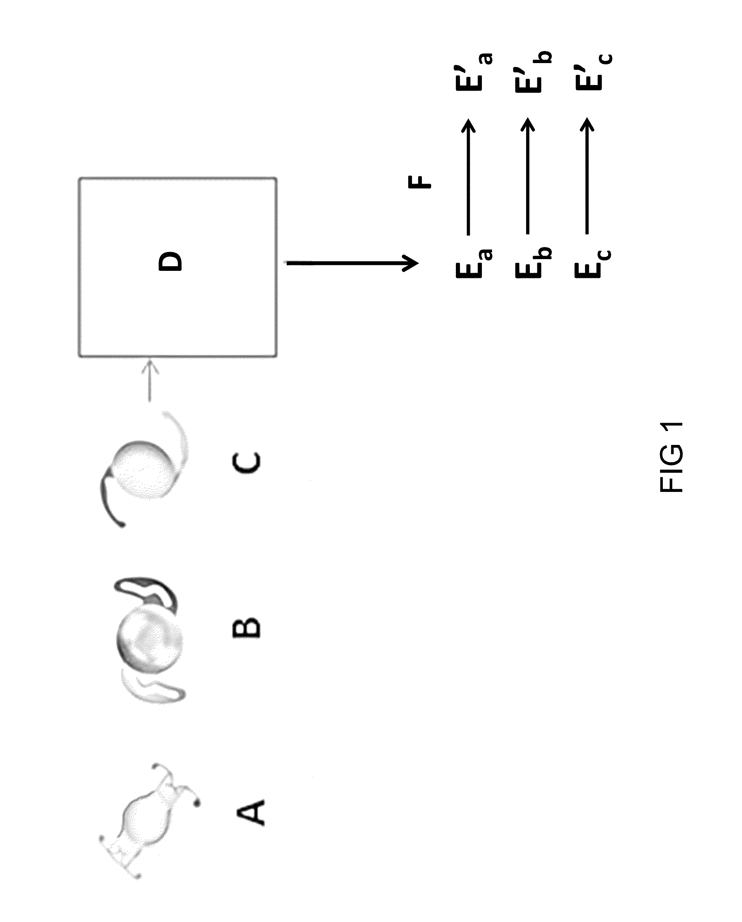
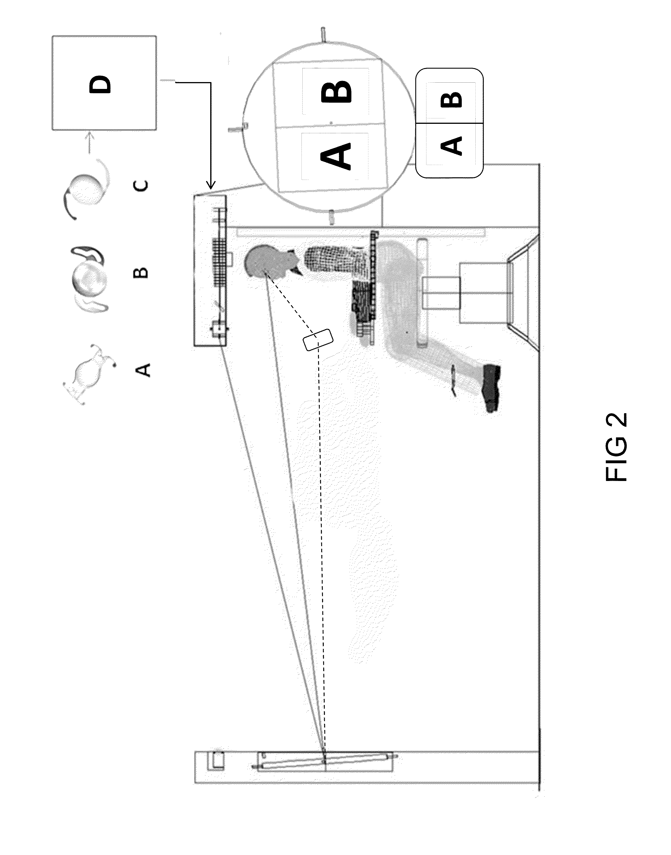
[0057]One embodiment of the apparatus has two components. An IOL measurement means is used to characterize the optical properties of one or more IOLs and to determine the modulation of the wavefront of an image that is necessary to reproduce or emulate the optical properties of the IOL once it is implanted in the patient's eye following removal of the patient's crystalline lens. The second component is an IOL emulator means that recreates the optical properties of the IOL for patient testing. In an alternative embodiment, the optical properties of the IOL are provided elsewhere.

[0058]FIG. 1 shows three multi-focal IOLs A, B, C that are made by different manufacturers and that have different optical designs. Three lenses are shown for exemplary purposes to illustrate the three major types of presbyopia correcting IOLs in use today; refractive, diffractive, and accommodating. The instrument is not limited to emulating these types of designs and it may be used to measure and emulate ne...


PUM


Abstract

A vision testing method and apparatus are disclosed, the method including measuring the modulation to a wavefront of light that is imparted by an intra-ocular lens, determining the wavefront modulation necessary to emulate the optical properties of the IOL after it replaces the crystalline lens in a patient's eye, generating a static or dynamic image viewable by a patient, modulating the wavefront of the image remote from the patient to attain the wavefront that necessary to emulate the optical properties of the IOL after it is implanted, and relaying said wavefront to a plane nearby, on, or within the patient's eye. The apparatus includes devices for measuring the modulation to a wavefront of light that is imparted by an intra-ocular lens, determining the wavefront modulation necessary to emulate the optical properties of the IOL after implantation in a patient's eye, generating a static or dynamic image viewable by a patient, modulating the wavefront of the image remote from the patient to attain the wavefront necessary to emulate the optical properties of the IOL after it is implanted, and relaying said wavefront to a plane nearby, on, or within the patient's eye.

Description

BACKGROUND OF THE DISCLOSURE[0001]1. Field[0002]Disclosed is a method and apparatus of simulating the optical properties of one or more intraocular lenses following implantation under real-world conditions at far away, close, and intermediate distances, and under monocular or binocular viewing conditions.[0003]2. Description of the Related Art[0004]Some fundamental optical concepts concerning presbyopia, cataracts, and cataract extraction and implantation of intraocular lenses are provided in order to facilitate an understanding of the method and apparatus.[0005]The convergence, or divergence, of light rays from an object is measured in optical units known as Diopters “D” where D=1 / F, and F is the distance between the object and its image in Meters. By convention, converging light is designated by a positive sign (+D) and diverging light is designated by a negative sign (−D).[0006]A normal eye has a converging optical power at rest of about +60D and it focuses distance objects to a ...

Claims


Application Information

Patent Timeline
Patent Type & Authority Applications(United States)
IPC IPC(8): A61B3/028
CPCA61B3/028A61B3/0025A61F2/1613A61F2009/0088G02C7/024A61B3/103A61F2240/002
Inventor THOMPSON, KEITH P.GARCIA, JOSE R.
Owner DIGITALVISION
Why Eureka
Try Eureka