
Apparatus and method for detecting DNA damage

a technology of dna damage and apparatus, applied in the field of apparatus and insitu method for detecting dna damage, can solve the problems of limiting the potential throughput of the assay, damage to the integrity of the dna of the cell, and high cost of the assay

Inactive Publication Date: 2013-07-11
GE HEALTHCARE LTD
View PDF3 Cites 7 Cited by
  • Summary
  • Abstract
  • Description
  • Claims
  • Application Information

AI Technical Summary

Benefits of technology

The present invention is about a device that can quickly and automatically detect DNA damage in cells from different types of tissue. This makes it easy to test the effects of different agents on DNA damage. It can also help evaluate the effects of environmental factors on DNA damage. This device helps conduct high-throughput testing of mutagenicity and monitoring of cells and tissues for DNA damage.

Problems solved by technology

Damage to the integrity of a cell's DNA may occur through a variety of mechanisms.
Any such DNA damage has the potential to lead to an inheritable defect in the genetic information carried by a cell and hence to potentiate the development of cancer.
The assays are typically extremely time consuming and expensive to perform (˜$50,000 / compound), and thus tend to be restricted to the end of the drug discovery process.
Some attempts have been made to adapt cell treatment steps of the protocol to the use of 96 well plates (Kiskinis, E. et. al., Mutagenesis, (2002), 17(1), 37-43); however assays continue to be carried out using microscope slides for electrophoresis and imaging, the preparation of which limits the potential throughput of the assay.
While this method provides an improvement over manual scoring of Comet assays, the method still uses microscope slides for electrophoresis separation of DNA and is therefore subject to most of the throughput limitations of traditional Comet assay methods.
However this method is intended for use with DNA separations of genomic DNA specifically for the purpose of avoiding physical damage to the DNA by shearing caused by pipetting of DNA solutions, and does not relate to handling of samples for measurement of DNA damage, nor to high-throughput analysis of DNA.

Method used


Image

  • Apparatus and method for detecting DNA damage
  • Apparatus and method for detecting DNA damage
  • Apparatus and method for detecting DNA damage

Examples


Embodiment Construction

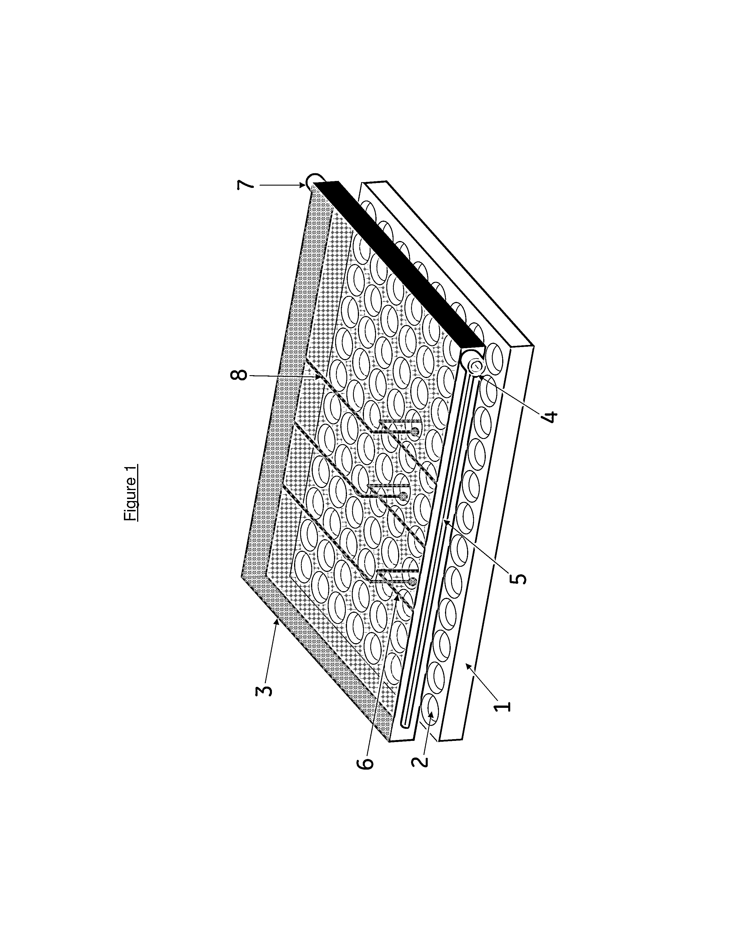
[0044]FIG. 1 shows a diagram of a 96-well plate [1] suitable for electrophoretic separation and microscopy imaging of DNA fragments (e.g. Packard View Plate, Packard). The plate [1] comprises an array of wells having optically transparent bases [2] which can be used to provide an array of separate vessels in which to carry out Comet assays. Cells are added to the wells [2] and where required, incubated with a test agent for an appropriate time period to allow potential DNA damage activity of the test agent to occur. Cells are overlaid with a suitable matrix to immobilise the cells. Cells are then treated with lysis and alkaline denaturation solutions by adding solutions to the wells, incubating and decanting. The wells of the plate are then filled with electrophoresis buffer, typically TBE (45 mM Tris-Borate, 1 mM EDTA pH 8.3) buffer and a moulded plastic plate lid [3] placed over the 96 well plate. The plate lid [3] supports electrodes and electrical connections suitable for applyi...


PUM

PropertyMeasurementUnit
temperaturesaaaaaaaaaa
pHaaaaaaaaaa
angleaaaaaaaaaa

Abstract

The invention relates to an apparatus and an in-situ method for detecting cellular DNA damage. The invention is particularly suited for use in Comet assays and for automation of such assays. The apparatus comprises a multiwell plate, the plate comprising an array of wells held in fixed relationship with each other and each well having an axis, side walls, and a base and wherein the well is provided with electrode pairs disposed therein; and wherein there is provided means for parallel connection of the electrode pairs to an external voltage supply.

Description

CROSS-REFERENCE TO RELATED APPLICATIONS[0001]This application is a divisional filing of U.S. patent application Ser. No. 12 / 746,169 filed Jun. 3, 2010, which is a filing under 35 U.S.C. §371 and claims priority to international patent application number PCT / EP2008 / 066895 filed Dec. 5, 2008, published on Jun. 11, 2009, as WO 2009 / 071665, which claims priority to patent application number 0723725.8 filed in Great Britain on Dec. 5, 2007.FIELD OF THE INVENTION[0002]The present invention relates to an apparatus and an in-situ method for detecting cellular DNA damage. The invention is particularly suited for use in Comet assays and for automation.BACKGROUND OF THE INVENTION[0003]Damage to the integrity of a cell's DNA may occur through a variety of mechanisms. DNA breakage may be caused through chemical reaction as a result of ingestion or absorption of a drug or other chemical agent which reacts with DNA (Exon, J. H., J. Toxicol. Environ. Health B Crit. Rev., (2006), 9(5), 397-412). Alt...

Claims


Application Information

Patent Timeline
Patent Type & Authority Applications(United States)
IPC IPC(8): G01N27/327
CPCB01L3/5085B01L2300/046B01L2300/0645G01N27/3275B01L2400/0421G01N27/44773B01L2300/0829
Inventor THOMAS, NICHOLASKENRICK, MICHAEL KENNETHSTUBBS, SIMON
Owner GE HEALTHCARE LTD
Learn More