Method for optimizing the working conditions of a cutting tool

Active Publication Date: 2013-07-11
AMVALOR
View PDF11 Cites 5 Cited by
  • Summary
  • Abstract
  • Description
  • Claims
  • Application Information

AI Technical Summary

Benefits of technology

[0013]One of the significant advantages of the invention lies in the fact that the tool/workpiece combination of a machining operation by the removal of chips is obtained directly on the production machine. There is no longer a need to instrument such a machine and to immobilize it to carry out the series of tests stipulated by the standard. The time saving is then considerable and is accompanied by a saving of costly equipment which is often not suited to use in a workshop—hence the need for a construction in a protected space of an instrumented machine dedicated to the tests, which is not negligible in terms of investment—and by a reduction in the number of the te

Problems solved by technology

Implementing these tests presents two drawbacks: the requirement to instrument the machine and the tool that is to be “predi

Method used


Image

  • Method for optimizing the working conditions of a cutting tool
  • Method for optimizing the working conditions of a cutting tool
  • Method for optimizing the working conditions of a cutting tool

Examples


Embodiment Construction

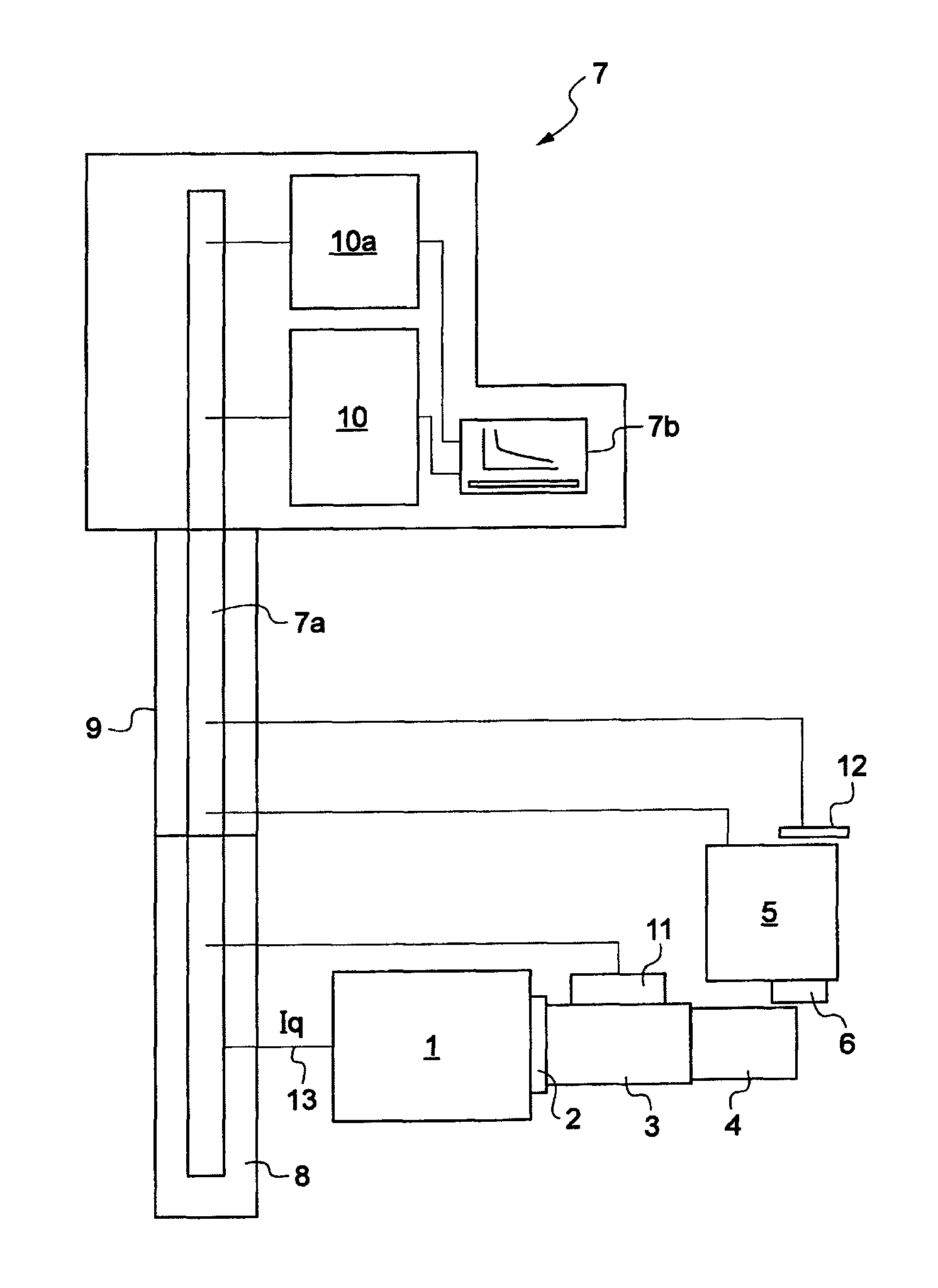
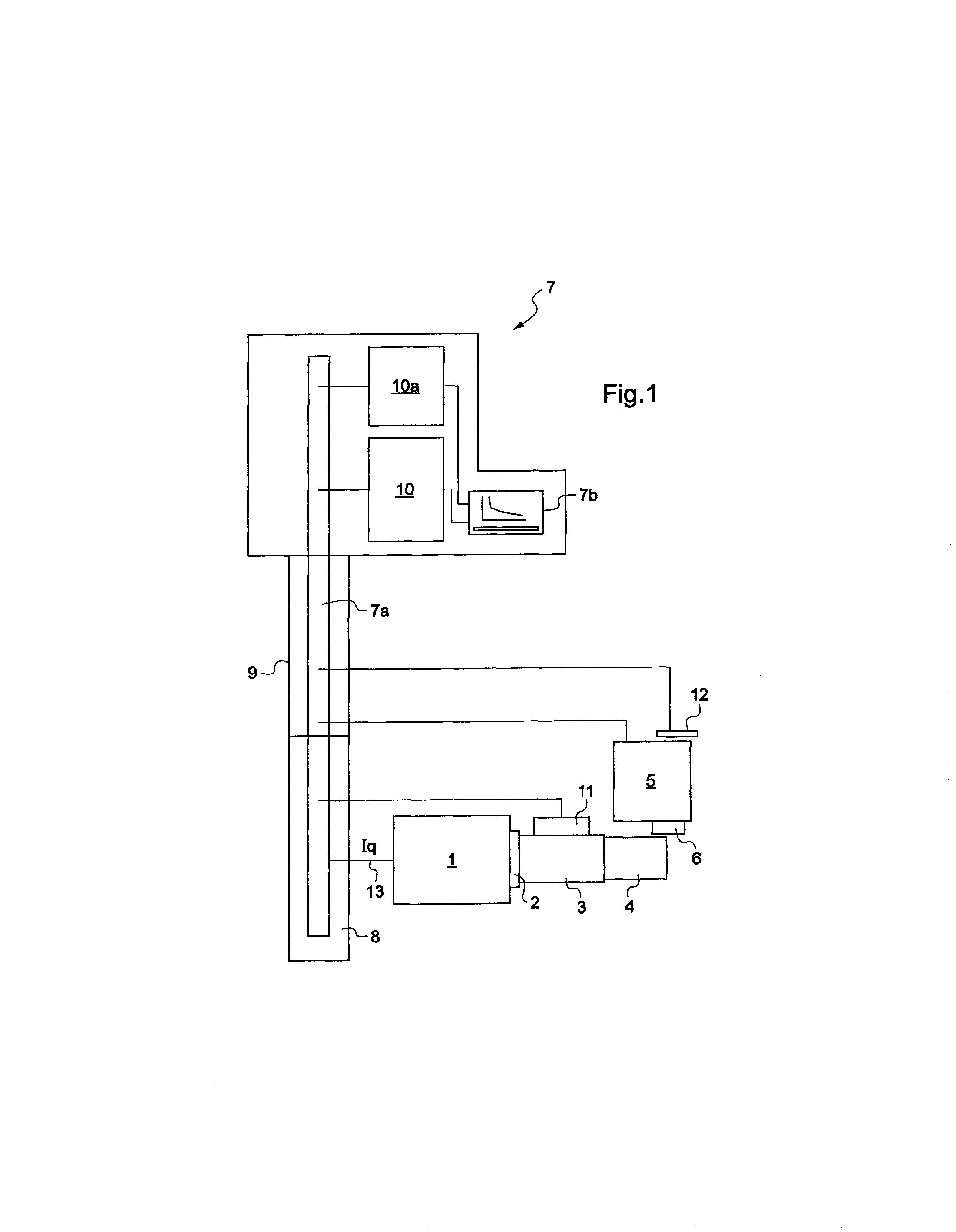
[0020]The diagram of FIG. 1 is that of a numerically-controlled machine intended for turning operations. To this end, a gear motor 1 is coupled by a transmission 2 to a spindle 3 which rotationally drives the parts to be machined 4. Moreover, the machine comprises a carriage 5, which can be displaced by a motor along a direction substantially parallel to the axis of the part to be turned, this carriage bearing a cutting tool 6 for machining the part 4.

[0021]The numerical control 7 is a programmable computer unit which acts on a regulator 8 of the power supply for the gear motor and on a regulator 9 of the motor driving the carriage 5, and does so according to machining software or a machining program 10. A communication bus 7a links the regulators to the numerical control and the latter to sensors 11 (coder) registering the rotation of the spindle, 12, of the displacement of the carriage. The regulator 8 computes, at each instant, the value of the torque current (Iq) of the spindle ...


PUM


Abstract

The invention relates to a method for acquiring the optimized parameters of a machining operation in the application of COM methodology, comprising: providing a plurality of readings indicative of the specific cutting energy (Kc) during an equal plurality of tests carried out with an imposed value, that is different from one test to another by at least one variable representative of the cutting operations, one of said variables being the cutting speed (Vc) and another being the advance rate (f); next determining a range of values of each of said variables including the optimal value for said variable obtained by means of processing the results for carrying out the machining operation; characterized in that a specific program (10a) of the digital control (7) is used for obtaining a continuous variation of the values of the variable during a single machining pass for a test, and in that the data read are formed during said single pass by the different values of the torque current (Iq) of the motor of the machine pin from which the corresponding values of (Kc) are derived by means of computational processing.

Description

BACKGROUND OF THE INVENTION[0001]1. Field of the Invention[0002]The present invention relates to a method for optimizing the working conditions of a cutting tool in the shaping of parts by the removal of chips, primarily turning, milling and drilling.[0003]2. Brief Discussion of the Related Art[0004]The aim of the French standard NF E66-520 is to define a method called Tool / Workpiece Combination (COM) intended to determine the working conditions of a cutting tool so as to deduce therefrom an optimum range of use in production. In practice, as recalled in the introduction to that standard: “These days, it is essential to get it right straight away while improving and predimensioning the production system.”[0005]Following the method recommended by this standard is a practice that has become fairly widespread these days. Very schematically, it will be recalled that the standard stipulates carrying out tests, after having defined a stable operating point for the tool and for the machine...

Claims


Application Information

Patent Timeline
IPC IPC(8): G05B19/416
CPCG05B19/401G05B19/4163G05B2219/49092
Inventor FROMENTIN, GUILLAUME
Owner AMVALOR
Why Eureka
Try Eureka