Sensor signal processing device

a signal processing and sensor technology, applied in the direction of machines/engines, electric control, instruments, etc., can solve the problems of inability to detect pre-ignition, engine output power or engine rotation malfunction, etc., and achieve the effect of reducing the signal processing load

Active Publication Date: 2013-07-11
DENSO CORP
View PDF40 Cites 15 Cited by
  • Summary
  • Abstract
  • Description
  • Claims
  • Application Information

AI Technical Summary

Benefits of technology

[0008]It is therefore an object to provide a sensor signal processing device, which is capable of reducing a signal processing load and detecting surely a pre-ignition even in a knock detection interval.

Problems solved by technology

The pre-ignition causes malfunction in engine output power or engine rotation.
However this detection method makes it impossible to detect the pre-ignition, when the pre-ignition is generated near the knock generation timing.

Method used


Image

  • Sensor signal processing device
  • Sensor signal processing device
  • Sensor signal processing device

Examples


Embodiment Construction

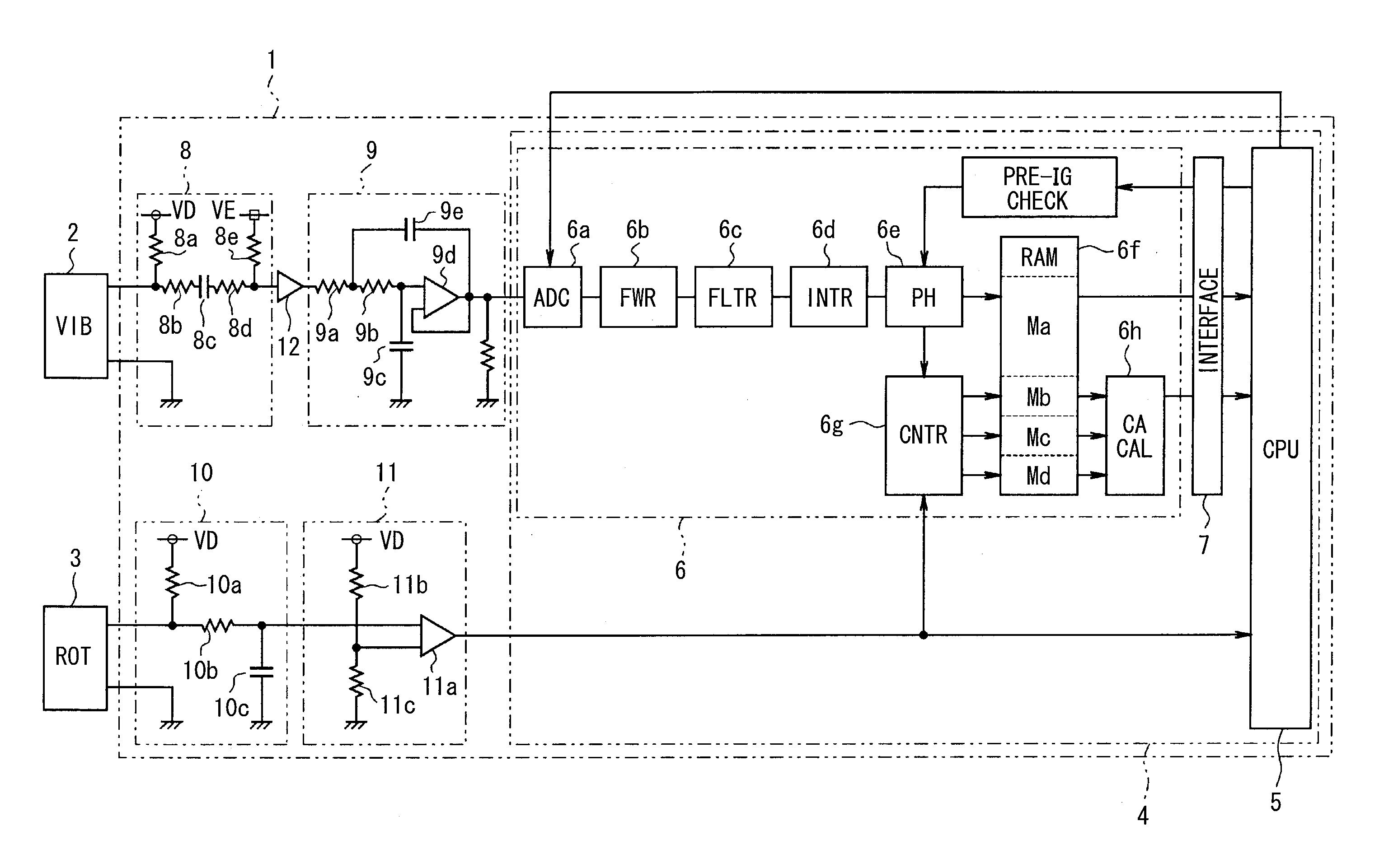
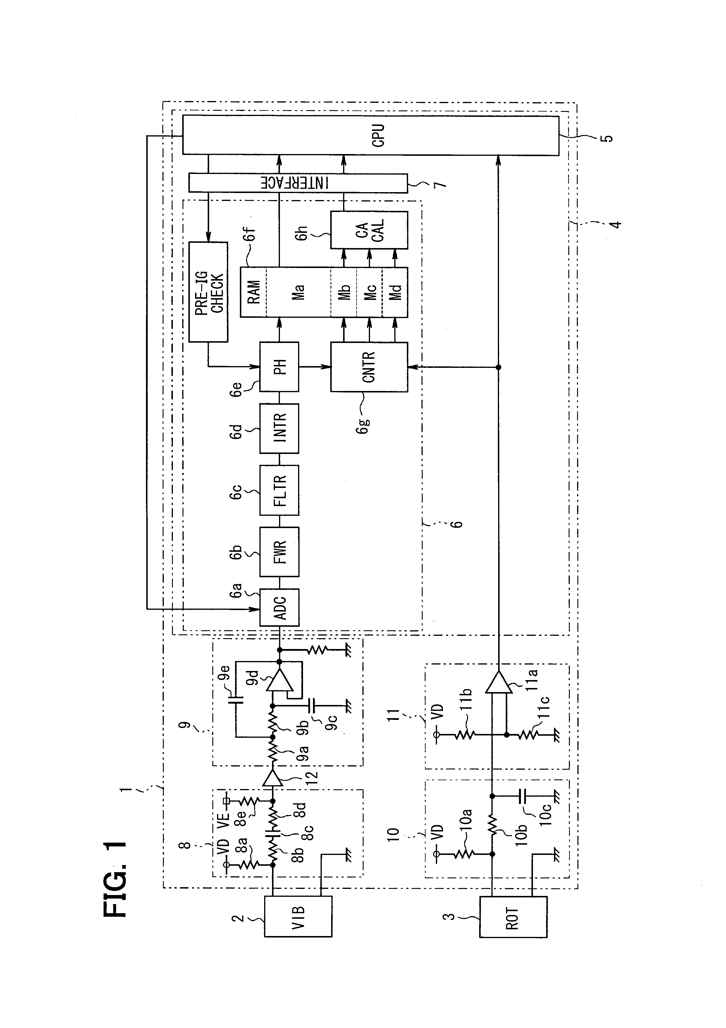
[0016]Referring to FIG. 1, a sensor signal processing device is implemented as an electronic control unit (ECU) 1, which receives signals from a vibration sensor 2 mounted on an engine (not shown) and a rotation sensor 3 for detecting a crankshaft rotation position (rotation angle).

[0017]The ECU 1 is formed of mainly a microcomputer (referred to as a computer) 4, which is a one-chip microcomputer formed as a semiconductor device including a CPU 5, a detection circuit 6 and a communication interface circuit 7 integrally. The CPU 5 is configured to communicate signals with the detection circuit 6 through the communication interface circuit 7. The CPU 5 has functions of operating as a check interval setting part, a crank angle interval setting part, a pre-ignition check part and a monitor part as described below. The ECU 1 includes a vibration sensor input circuit 8 and a filter circuit 9 for retrieving a detection signal of the vibration sensor 2 into the computer 4. The ECU 1 also in...


PUM


Abstract

A microcomputer is formed of a CPU and a detection circuit and inputs sensor signals of a vibration sensor and a rotation sensor. The detection circuit includes an AD converter circuit for AD conversion of the sensor signal of the vibration sensor at a predetermined sampling interval, a peak hold circuit for detecting a peak value of the sensor signal, a RAM for storing the peak value, a counter for detecting a crank angle at a peak value detection time, and an angle calculation part. The microcomputer divides a pre-ignition check interval into plural interval units and checks the pre-ignition based on the peak value detected in each unit interval. The pre-ignition and the knock are checked by using different threshold values in an interval, in which the pre-ignition check interval overlaps a knock check interval.

Description

CROSS REFERENCE TO RELATED APPLICATION[0001]The present application is based on and incorporates herein by reference Japanese patent application No. 2012-3010 filed on Jan. 11, 2012.TECHNICAL FIELD[0002]The present disclosure relates to a sensor signal processing device for an engine.BACKGROUND ART[0003]As one abnormal combustion condition among various combustion conditions of an engine, air-fuel mixture is ignited by itself for some reason without ignition spark in the midst of compression stroke of the engine. This is referred to as a pre-ignition. The pre-ignition causes malfunction in engine output power or engine rotation.[0004]It is thus necessary to control the engine by detecting such a pre-ignition. The pre-ignition may be detected generally by comparing an ignition timing and an abnormal vibration generation timing. For this detection, the abnormal vibration generation timing need be detected accurately. The pre-ignition varies its magnitude very much and frequently occur...

Claims


Application Information

Patent Timeline
Patent Type & Authority Applications(United States)
IPC IPC(8): F02D35/02
CPCF02D2041/281F02D35/027F02D35/023F02D37/02F02D2041/1432F02D2041/286F02P5/152F02P5/1522
Inventor KAWAKAMI, DAISUKEITOU, AKITOKUNO, RYOTARO
Owner DENSO CORP
Why Eureka
Try Eureka