Conductive dust dectection

a technology of conductive dust and dectection, which is applied in the field of conductive dust dectection, can solve the problems of affecting the reliability of the system, short circuiting of one or more electronic components within the rack, and affecting the ability of the system to operate normally, so as to facilitate the passage of airflow

Inactive Publication Date: 2013-07-18
IBM CORP
View PDF10 Cites 17 Cited by
  • Summary
  • Abstract
  • Description
  • Claims
  • Application Information

AI Technical Summary

Benefits of technology

[0003]The shortcomings of the prior art are overcome and additional advantages are provided through the provision of an apparatus which comprises a dust detector, a voltage source and a controller. The dust detector includes: two opposing surfaces disposed in spaced, opposing relation with a gap therebetween to facilitate passage of an airflow between the two opposing surfaces; and a conductive dust sensor, disposed at one surface of the two opposing surfaces. The voltage source establishes an electrostatic field at least partially between the two opposing surfaces, wherein the electrostatic field facilitates directing, at least in part, conductive particles in the airflow passing between the two opposing surfaces towards the conductive dust sensor. The controller monitors for a leakage current within the conductive dust sensor, and determines whether the leakage current exceeds a predetermined trigger level indicative of the presence of conductive dust, and responsive to the leakage current exceeding the predetermined trigger level, automatically indicates a conductive dust warning.

Problems solved by technology

This trend poses challenges at both the module and system level.
Within a data center, this conductive dust can include, for example, salt contaminants that have a deliquescent relative humidity above which the salt will absorb moisture, become wet and create ionic bridges, which may potentially cause short circuiting of one or more electronic components within the rack.
For example, conductive dust can cause electrical short circuiting of closely spaced electrical features on circuit boards or other components with exposed metal traces, and thereby degrade system reliability.
If the dust is found to be conductive at the existing relative humidity level, then component damage may occur, and the data center might need to be cleaned and any failed system hardware replaced.

Method used


Image

  • Conductive dust dectection
  • Conductive dust dectection
  • Conductive dust dectection

Examples


Embodiment Construction

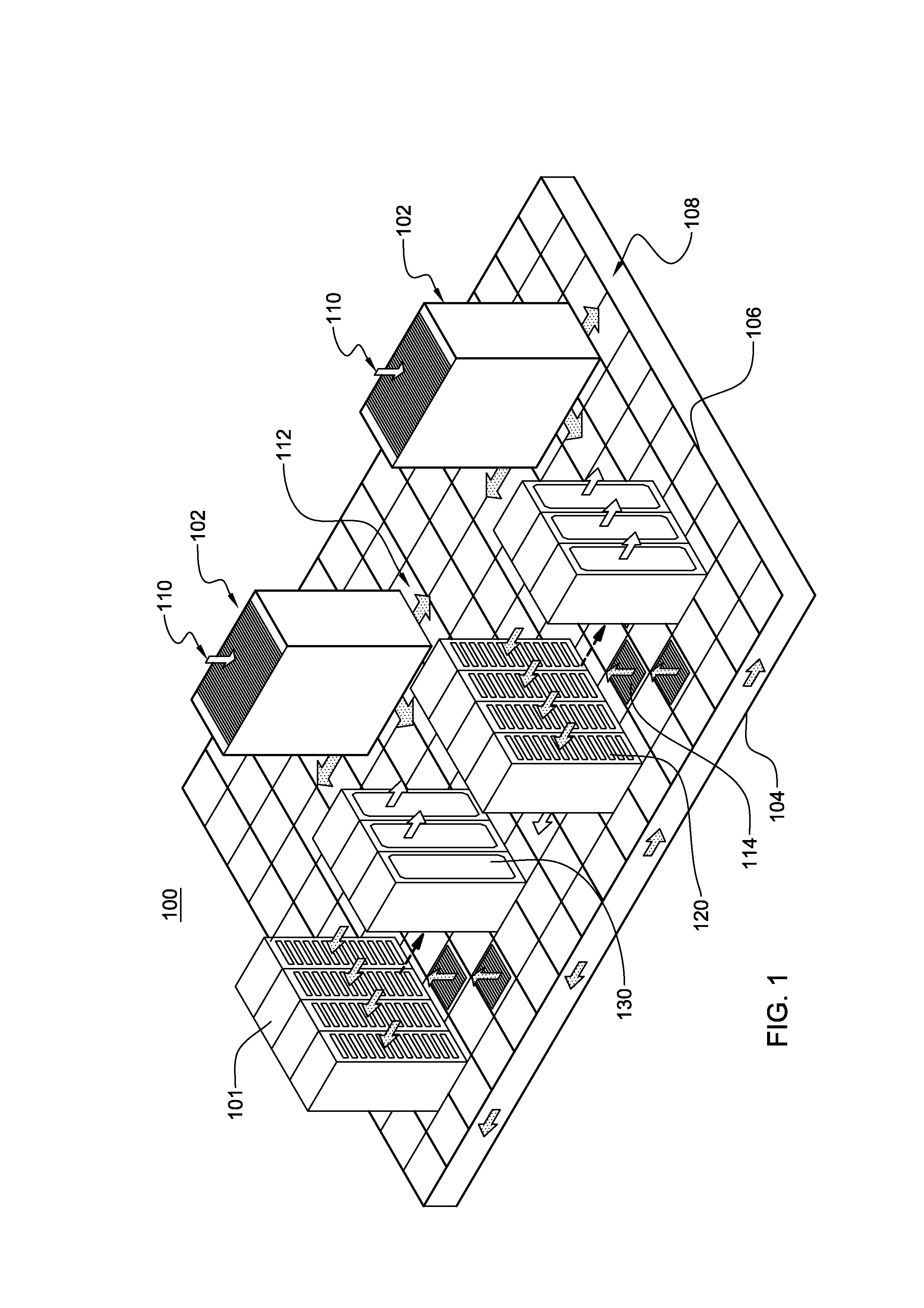
[0019]As used herein, the term “electronics rack”, includes any housing, frame, rack, compartment, blade server system, etc., having one or more heat generating components of a computer system or electronic system, and may be, for example, a stand-alone computer processor having high, mid or low end processing capability. In one embodiment, an electronics rack may comprise multiple electronic systems, each having one or more heat generating components disposed therein requiring cooling. “Electronic system” refers to any sub-housing, blade, book, drawer, node, compartment, etc., having one or more heat generating electronic components disposed therein. Each electronic system of an electronics rack may be movable or fixed relative to the electronics rack, with the central electronic complex (CEC) nodes of an IBM System z® mainframe computer being one example of electronic systems of an electronics rack. Further, “data center” refers to a computer installation containing one or more el...


PUM


Abstract

An apparatus is provided, which includes a dust detector, a voltage source, and a controller. The dust detector includes two opposing surfaces and a conductive dust sensor. The two opposing surfaces are disposed in spaced, opposing relation to allow for the passage of airflow between the surfaces, and the conductive dust sensor is disposed at a surface of the two opposing surfaces. The voltage source is configured and controlled to establish an electrostatic field at least partially between the two opposing surfaces to facilitate directing conductive particles in the airflow passing between the two opposing surfaces towards the dust sensor. The controller monitors for a leakage current within the conductive dust sensor and determines whether the leakage current exceeds a predetermined trigger level indicative of the presence of conductive dust, and if so, automatically indicates a conductive dust warning.

Description

BACKGROUND[0001]In many large server applications, processors along with their associated electronics (e.g., memory, disk drives, power supplies, etc.) are packaged in removable node configurations stacked within an electronics (or IT) rack or frame. In other cases, the electronics may be in fixed locations within the rack or frame. Typically, the components are cooled by air-moving in parallel airflow paths, usually front-to-back, impelled by one or more air-moving devices (e.g., fans or blowers). The power dissipation of integrated circuit chips, and the modules containing the chips, continues to increase in order to achieve increases in processor performance. This trend poses challenges at both the module and system level. In certain cases it may be possible to handle increased power dissipation within a single node by providing greater airflow, through the use of a more powerful air-moving device or by increasing the rotational speed (i.e., RPMs) of an existing air-moving device...

Claims


Application Information

Patent Timeline
Patent Type & Authority Applications(United States)
IPC IPC(8): G05D22/02F24F3/14G01R31/02
CPCG01N2015/0046H05K7/20736H05K7/20181G01N15/0656
Inventor KUCZYNSKI, JOSEPHMILLER, MELISSA K.SINGH, PRABJITWILLIAMS, HEIDI D.ZHANG, JING
Owner IBM CORP
Why Eureka
Try Eureka