Simplified LNG Process

a technology of lng and process, applied in the direction of cold treatment separation, liquefaction, solidification, etc., can solve the problems of pipelines that cannot be economically justified, gas volume is not enough, and the formidable problem of liquefying fuel, etc., to achieve the effect of producing lng on a small scal

a technology of lng and process, applied in the direction of cold treatment separation, liquefaction, solidification, etc., can solve the problems of pipelines that cannot be economically justified, gas volume is not enough, and the formidable problem of liquefying fuel, etc., to achieve the effect of producing lng on a small scal

US20130180282A1Active Publication Date: 2013-07-189052151 CANADA

Image

  • Simplified LNG Process
  • Simplified LNG Process

Examples


Embodiment Construction

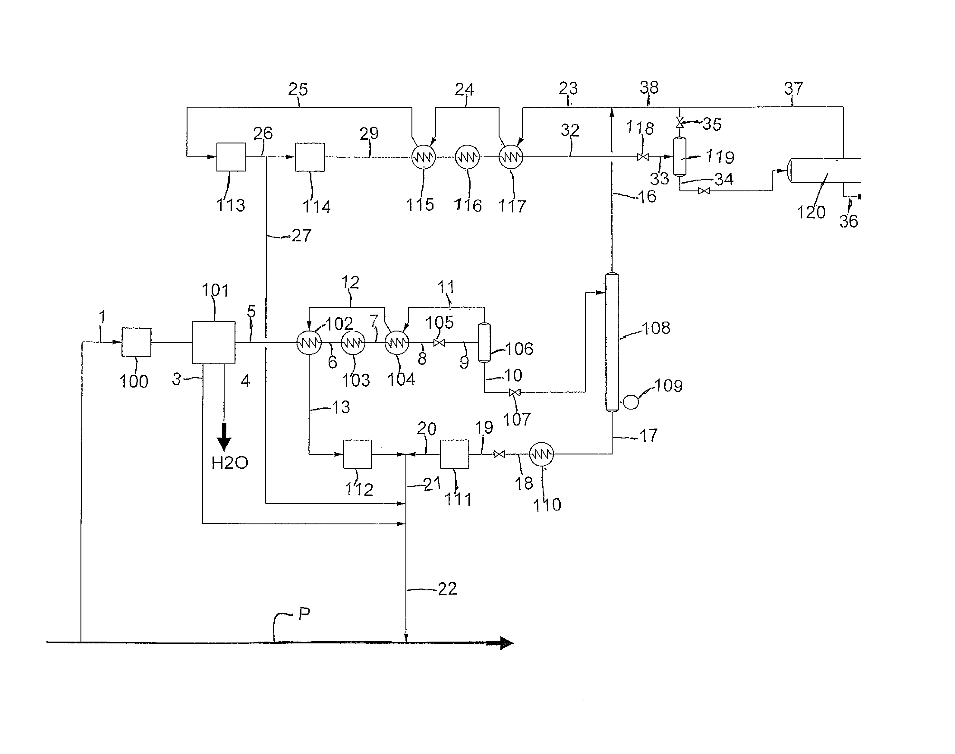
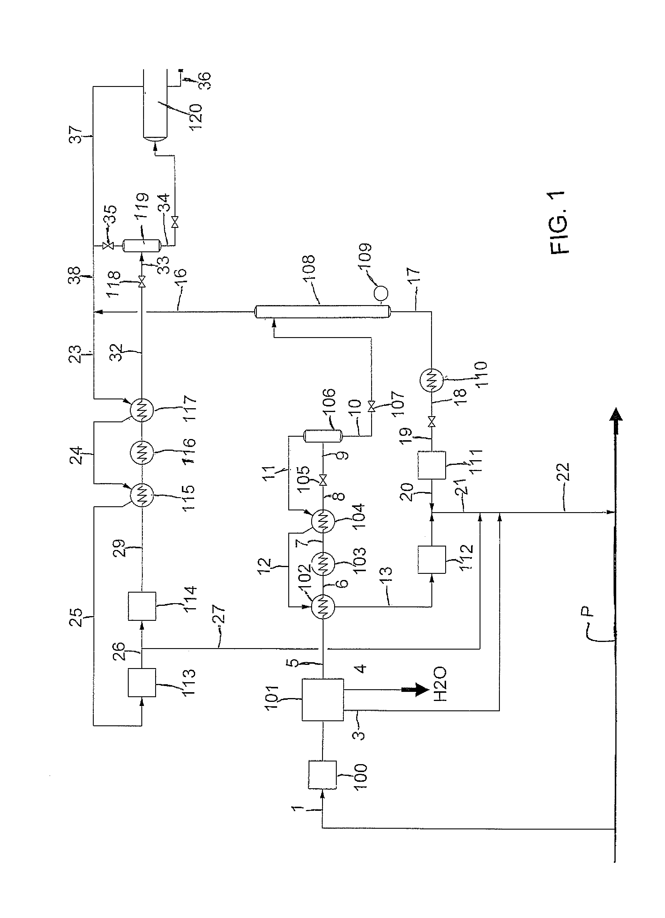
[0028]The process as shown in FIG. 1 proceeds in two stages. The first stage 1 is the purification step where unwanted gases such as CO2, water vapour, sulphur compounds and gases lighter than or heavier than methane are excluded from the feed gas 1.

[0029]The Feed gas at stream 1 from the pipe line P is fed to a compressor 100 and then to a stream to an adsorption unit 101. Since the LNG process is cryogenic it is also necessary to exclude CO2 and water vapour from the gas in unit 101 to avoid freezing problems in the low temperature equipment. Water is discharged in stream 4. The feed gas at stream 5.

[0030]The first stage separates the feed gas into two streams 16 and 21.

[0031]The first stream 16 is a cold stream that has sufficient of the contaminants extracted to meet product specifications for composition of the LNG and the second stream 21 that contains a significant quantity of the original natural gas from the natural gas supply plus substantially all of the components reject...


PUM


Abstract

A simplified method for production of a commercial supply liquefied natural gas (LNG) supplied in a pressurized vessel includes taking a supply of natural gas including contaminants from a stranded well or from a pipe line and extracting from the supply gas water vapor and CO2 in a fixed bed absorption system. In a first stage the supply gas is separated into first and second streams where the first stream contains all the cold energy available from the feed stream and sufficient of the contaminants are removed to meet a product specification for the composition of the LNG supply. In a second stage the first stream is liquefied by the available cool energy for commercial pressurized supply container The second stream contains natural gas which is as much as 75% of the feed stream together with substantially all the contaminants and is used as a natural gas supply.

Description

[0001]This invention relates to method for production of liquefied natural gas (LNG).BACKGROUND OF THE INVENTION[0002]Liquefied Natural gas, LNG, is primarily methane, propane and other heavier hydrocarbons. Producers of LNG until recently had considerable flexibility in the specifications of the gas that they liquefied, but there is now a trend toward tightening the composition requirements for LNG, specifically in North America which has seen the current standards for methane content approaching 100%. This means that in order to meet the new standards of these markets, producers of LNG are faced with not only the formidable problem of liquefying the fuel, but also using cryogenic fractionation to exclude the undesirable components such as helium, nitrogen, CO2, ethane, propane and heavier from the mixture.[0003]The production of LNG is most applicable in situations where the source of the gas is an isolated field so far from markets for the gas that a pipeline cannot be economical...

Claims


Application Information

Patent Timeline
18 Jul 2013
Publication
US20130180282A1
IPC
F25J1/00
CPC
F25J1/0022; F25J1/004; F25J1/0208; F25J1/0232; F25J1/0254; F25J2205/04; F25J2290/62; F25J2220/64
Inventors
PALMER, GARY