Nasal delivary device

Active Publication Date: 2013-07-18
SIPNOSE
View PDF5 Cites 33 Cited by
  • Summary
  • Abstract
  • Description
  • Claims
  • Application Information

AI Technical Summary

Benefits of technology

The present invention provides an air-intake actuated device for delivering a substance to a nasal cavity of a subject. The device includes a container for containing the substance, a nosepiece for placement in the nasal cavity, a valve mechanically connected to the container, and a trigger mechanism. The trigger mechanism is activated by the subject intaking air through a mouthpiece, and can reconfigure the valve from an active configuration to an inactive configuration and vice versa. The device can deliver the substance in a predetermined amount and for a predetermined period of time. The device is sterilizable, and can be used with an external container to fill the container with the substance. The device can also include indicating means to indicate the amount of substance within the container. The technical effects of the invention include improved delivery of substances to the nasal cavity, synchronization with the intake of air, and the ability to reconfigure the valve from an active to an inactive configuration and vice versa.

Problems solved by technology

On the other hand, the limitations of nasal delivery of a substance are:
(a) the histological toxicity of absorption enhancers used in nasal drug delivery system is not yet clearly established; (b) relatively inconvenient to patients when compared to oral delivery systems since there is a possibility of nasal irritation; (c) nasal cavity provides smaller absorption surface area when compared to (Gastro intestinal tract GIT).
These drugs are unsuitable for oral administration because they are significantly degraded in the gastrointestinal tract or considerably metabolized by first pass effect in the liver.
Also, the parenteral route is inconvenient for long term therapy.
These traditional devices have not generally been able to achieve the particle sizes necessary to maximize efficacy while helping mitigate undesired pulmonary absorption.

Method used


Image

  • Nasal delivary device
  • Nasal delivary device
  • Nasal delivary device

Examples


third embodiment

[0270] the inhaling-actuating device 700 comprises a mouthpiece 502, a nosepiece 504 and an actuator 531 rotated around a hinge 530 (see FIG. 29).

[0271]FIG. 30 illustrates a cross sectional view of the same. In the Fig. is can be seen that the hinge 530, around which said actuator 531 is rotated, is mechanically coupled to a spring 532 by means of a connector 533. Said spring 532 is maintained retracted (i.e., loaded) by means of a casing 534 (as will be disclosed hereinafter). Said inhaling-actuating device 700 further comprises a container for containing a medicament 506 (not shown).

[0272]Reference is now made to FIGS. 31-35, illustrating the actuation of device 700.

[0273]FIG. 31 illustrates device 700 prior to the actuation. FIG. 32 illustrates the first step of the actuation in which actuator 531 is rotated around hinge 530. said rotation engage spring 532 and loads the same (i.e., compress the same). A second spring 535, encased within a casing 536 is linearly moved along a pat...

case 534

[0274]Case 534 of spring 532 is characterized by at least one groove 537 into which at least a portion of casing 536 of spring 535 is inserted so as to maintain spring 532 loaded.

[0275]As mentioned, said movement of said spring 535 and casing 536 engages with the casing 534 of spring 532 (namely inserted into groove 537) so as to spring 532 loaded (compressed).

[0276]FIGS. 33-34 illustrate the next step, in which medicament 506 is loaded into device 700.

[0277]FIG. 35 illustrates the final step in which the device 700 is actuated.

[0278]As described above, the activation in initiated by the intake of air by the user. Once the user inhale (see arrows 538) a membrane 508 (which is mechanically coupled to spring 535) is withdrawn away from spring 532. said movement of said membrane withdraw also said spring 535 and casing 536 (from groove 537 of spring 532).

[0279]Said withdraw unload spring 532 and the same is retracted to the initial position. Said retraction is characterized by a piston...

fourth embodiment

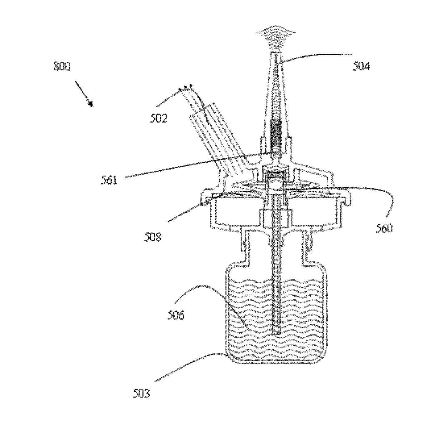
[0283]Reference is now made to FIGS. 39-41, illustrating the inhaling-actuating device 800. According to this embodiment, the device 800 comprises a container 503 containing a medicament 506 to be delivered to the nasal cavity, a unidirectional valve 560, an intermediate container 511, a second unidirectional valve 561 and a membrane 508.

[0284]Prior to the actuation of the device 800 the intermediate container 511 is filled with a uni-dose amount of medicament 506 (this is enabled due to the fact that once the medicament is release to the nasal cavity, vacuum is generated within the intermediate container 511; thus, medicament is withdrawn into the same through unidirectional valve 561).

[0285]Once the patient intake air (see FIG. 40), device 800 is actuated. Reference is now made to FIG. 40 illustrating the actuation mechanism.

[0286]Once the user inhale air (see arrows 562), membrane 508 is elevated. Membrane 508 is mechanically coupled to said valve 560, such that when said membran...


PUM

PropertyMeasurementUnit
Timeaaaaaaaaaa
Diameteraaaaaaaaaa
Lengthaaaaaaaaaa

Abstract

It is one object of the present invention to provide an air-intake actuated device adapted for delivering a substance to a nasal cavity of a subject, comprising:a. a container for containing said substance;b. a nosepiece extending from said device for placement in proximity to a nose of said subject.c. a valve mechanically connectable to said container, characterized by an ACTIVE CONFIGURATION and an INACTIVE CONFIGURATION; and,d. a trigger mechanism adapted to reconfigure said valve from said ACTIVE CONFIGURATION to said INACTIVE CONFIGURATION, and vice versa;wherein said trigger mechanism is activated by means of said subject intaking air through said mouthpiece;further wherein said trigger mechanism is adapted to reconfigure said valve from said INACTIVE CONFIGURATION to said ACTIVE CONFIGURATION for a predetermined period of time in response to said subject intake of air.

Description

FIELD OF THE INVENTION[0001]The present invention generally relates to a nasal substance delivery device, and more specifically, to a drinking / breathing -actuated device for delivering a substance to a nasal cavity of a subject in a variety of different delivery methods.BACKGROUND OF THE INVENTION[0002]Nasal delivery of a substance (e.g., a drug, a vaccine, etc.) can be useful both for treating diseases or disorders in the nasal passageways themselves and for treating other disorders or conditions trough the systemic route (e.g., vaccine, neurological, etc.). The advantages of nasal delivery of a substance are among others the following:[0003](a) rich vascular plexus- direct route into the blood stream; (b) avoiding gastrointestinal destruction as drug degradation that is observed in the gastrointestinal tract is absent. (c) Hepatic first pass metabolism (destruction of drugs by liver enzymes) is absent; (d) rates of absorption and plasma concentrations are comparable to intravenous...

Claims


Application Information

Patent Timeline
IPC IPC(8): A61M15/08
CPCA61M11/00A61M15/00A61M15/08A61M2016/0015A61M16/207A61M2210/0618A61M2210/0625A61M15/0091A61M16/20A61M2202/064A61M15/0093A61M16/201A61M11/02A61M11/006A61M2202/30A61K39/00A61M15/0016A61M15/003A61K9/0043A61K2039/543A61M15/009
Inventor SHAHAF, DANIELHADASH, JOSEPH
Owner SIPNOSE
Why Eureka
Try Eureka