Communication system

a communication system and communication system technology, applied in broadcast transmission systems, machine-to-machine/machine-type communication services, network topologies, etc., can solve problems such as reducing data rates, henb, user equipment (ue), and rach involving collision risks, so as to reduce data volume, prevent communication system from becoming complicated, and mitigate the congestion of the core network

Active Publication Date: 2013-07-18
MITSUBISHI ELECTRIC CORP
View PDF4 Cites 21 Cited by
  • Summary
  • Abstract
  • Description
  • Claims
  • Application Information

AI Technical Summary

Benefits of technology

[0076]According to the communication system of the present invention, when receiving the data transmitted from the plurality of communication terminal devices to the core network, the base station device performs the concentration process of concentrating the received data on the plurality of terminal device groups and transmits the data obtained through the concentration process to the core network. The concentration process is performed on a plurality of terminal device groups in this manner, so that even in a case where a large number of terminal device groups to be served by a base station device are located, the number of communication times from a base station device to a core network or amount of data can be reduced. Accordingly, even in a case where a large number of terminal device groups to be served by a base station device are located, it is possible to mitigate the congestion of the core network in a situation in which data needs to be communicated with a large number of communication terminal devices included therein.
[0077]Further, the data to be transmitted from the communication terminal device to the core network is transmitted to the core network after the concentration process by the base station device. Accordingly, even in a case where the communication terminal device is installed in a poor radio environment, communication with the communication terminal device is allowed, where the base station device serves as an origin. This does not require to separately provide, for example, a device such as a concentrator between the communication terminal device and the base station device, so that the communication system can be prevented from becoming complicated.
[0078]These and other objects, features, aspects and advantages of the present invention will become more apparent from the following detailed description of the present invention when taken in conjunction with the accompanying drawings.

Problems solved by technology

The RACH involves a collision risk.
In a case where the HeNB is installed in the coverage of the macro cell, interference occurs among the macro cell, HeNB, user equipment (UE), and the like.
The above-mentioned interference hinders the communication between the user equipment (UE) and the macro cell or HeNB, which reduces a data rate.
Further increased interference power disables communication.
This causes a problem that a core network is congested.

Method used


Image

  • Communication system
  • Communication system
  • Communication system

Examples


first embodiment

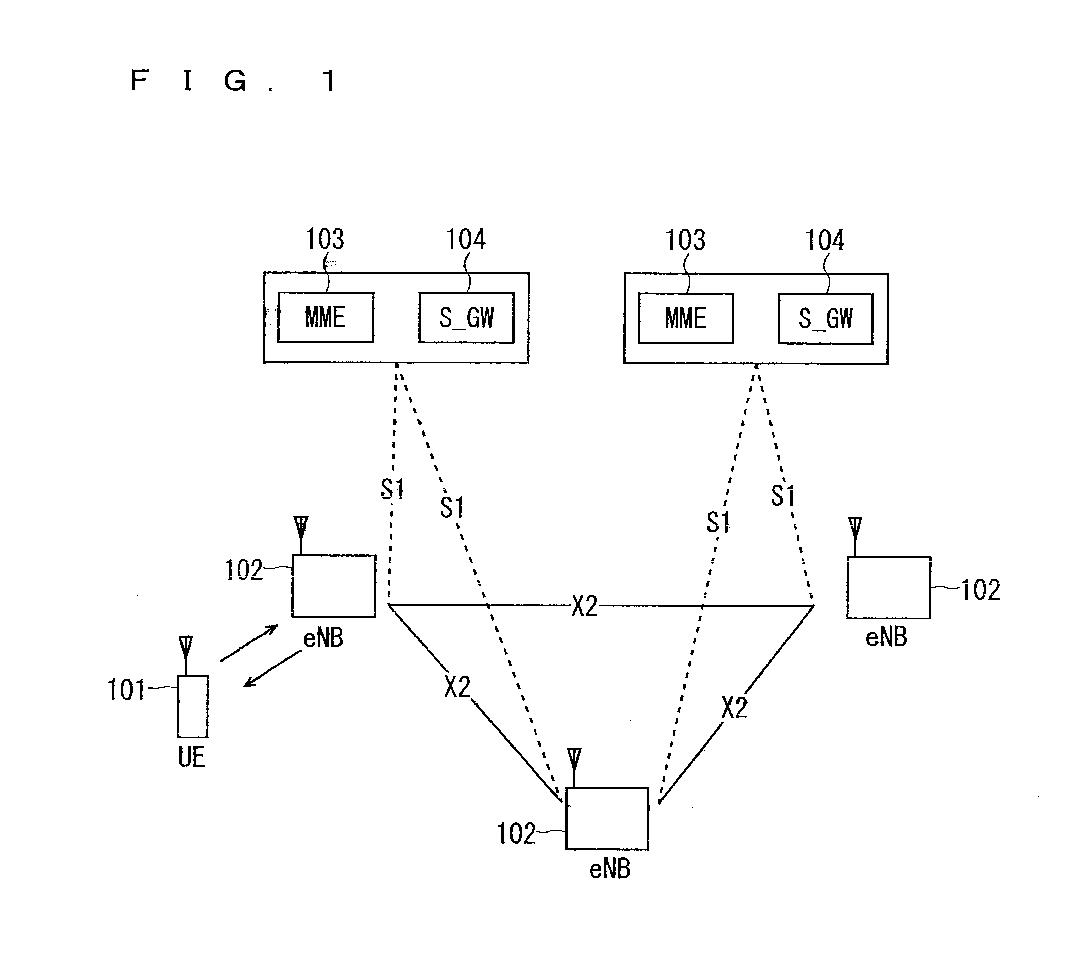
[0123]FIG. 7 is a block diagram showing an overall configuration of an LTE mobile communication system, which is currently under discussion of 3GPP. Currently, 3GPP is studying an overall system configuration including closed subscriber group (CSG) cells (Home-eNodeBs (Home-eNB; HeNB) of E-UTRAN, Home-NB (HNB) of UTRAN) and non-CSG cells (eNodeB (eNB) of E-UTRAN, NodeB (NB) of UTRAN, and BSS of GERAN) and, as to E-UTRAN, is proposing the configuration as shown in FIG. 7 (see Chapter 4.6.1 of Non-Patent Document 1).

[0124]FIG. 7 is described. A user terminal device (hereinafter, referred to as “user equipment” or “UE”) 71 is capable of performing radio communication with a base station device (hereinafter, referred to as “base station”) 72 and transmits / receives signals through radio communication. The user terminal device is equivalent to a communication terminal device. Hereinafter, the user terminal device is refereed to as “communication terminal” in some cases. The base stations ...

second embodiment

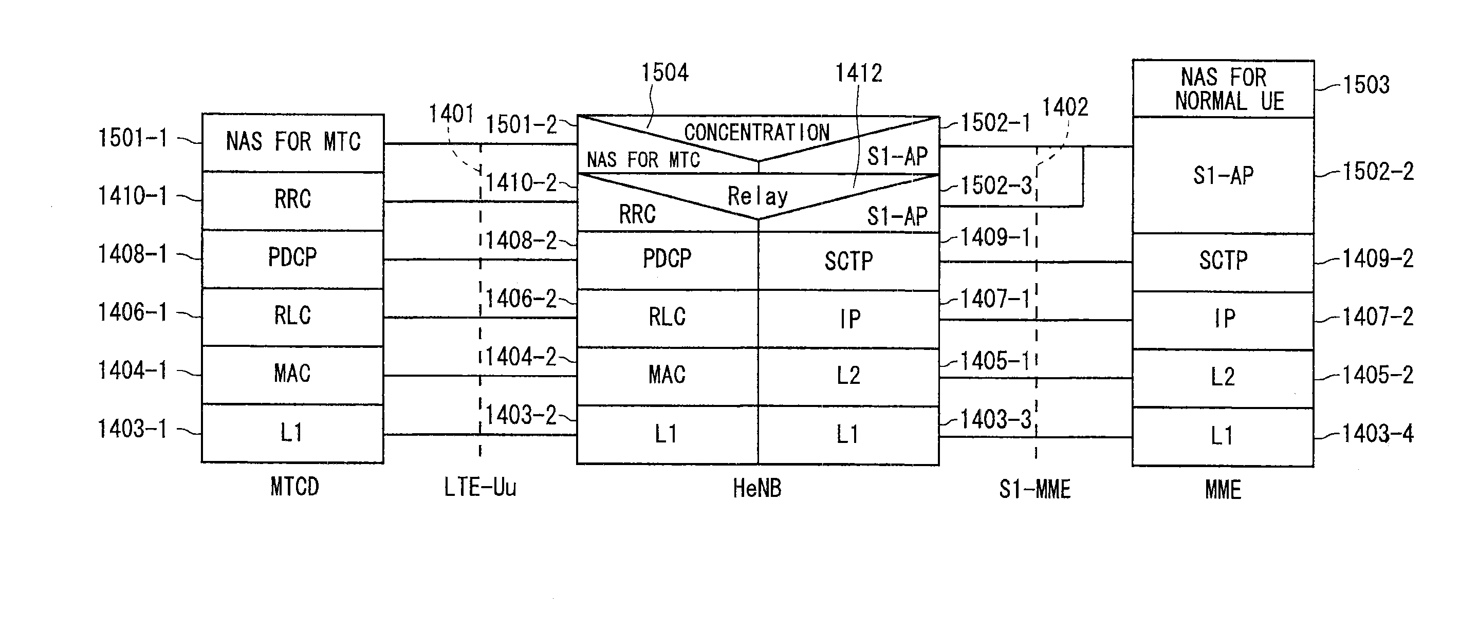
[0306]A second embodiment discloses a specific method of transmitting data from a HeNB to an MME, SGSN, or the like being a core network after the HeNB performs a concentration process using the first embodiment.

[0307]A solution in the second embodiment is described below. A HeNB serves as a trigger or origin, and transmits data from an MTCD being served thereby to an MME, SGSN, MTC server, or the like being a core network.

[0308]The following two (1) and (2) are disclosed as specific examples of the condition that a HeNB serves as a trigger of the data transmission to an MME, SGSN, MTC server, or the like being a core network from an MTCD being served thereby.

[0309](1) A HeNB transmits the data from an MTCD being served thereby to a core network irrespective of the reception of the uplink data from the MTCD being served thereby. This transmission may be performed over the resources for MTCD. Specific examples of the resources for MTCD include a time at which the communication for MT...

third modification

of Second Embodiment

[0365]A third modification of the second embodiment discloses another specific example of the second embodiment when the HeNB transmits the data from an MTCD being served thereby to an MME, SGSN, MTC server, or the like being a core network via the MME by means of the S1 interface. The existing S1 signaling or S1 message is used. The existing S1 signaling for control may be used. Alternatively, the existing S1 signaling associated with a user equipment may be used. The existing S1 signaling associated with a user equipment is also referred to as “UE associated Signalling” (see Non-Patent Document 14).

[0366]The following nine (1) to (9) are disclosed as specific examples of the parameters required for the existing S1 signaling when a HeNB transmits the data from an MTCD being served thereby to an MME, SGSN, MTC server, or the like being a core network via the MME by means of the S1 interface.

[0367](1) HeNB identity. This may be a physical cell identity (PCI), cell...


PUM


Abstract

The present invention has an object to provide a communication system capable of mitigating, even if a large number of terminal device groups to be served by a base station device are located, congestion of a core network in a situation in which data is required to be communicated from the large number of communication terminal devices or to the large number of communication terminal devices at the same time. In the present invention, when judging to have received an RRC message from a communication terminal device (UE) in Step ST1601, a base station device, for example, HeNB checks an MTCD indicator to be mapped to the received RRC message in Step ST1602. Then, when judging that the UE that has transmitted the RRC message received in Step ST1601 is an MTCD being a device for machine type communication (MTC) from the checked MTCD indicator, the HeNB performs a concentration process on the data from the MTCD to the core network in Step ST1604.

Description

TECHNICAL FIELD[0001]The present invention relates to a communication system in which a base station device performs radio communication with a plurality of communication terminal devices.BACKGROUND ART[0002]Commercial service of a wideband code division multiple access (W-CDMA) system among so-called third-generation communication systems has been offered in Japan since 2001. In addition, high speed downlink packet access (HSDPA) service for achieving higher-speed data transmission using a downlink has been offered by adding a channel for packet transmission (high speed-downlink shared channel (HS-DSCH)) to the downlink (dedicated data channel, dedicated control channel). Further, in order to increase the speed of data transmission in an uplink direction, service of a high speed uplink packet access (HSUPA) system has been offered. W-CDMA is a communication system defined by the 3rd generation partnership project (3GPP) that is the standard organization regarding the mobile communi...

Claims


Application Information

Patent Timeline
Patent Type & Authority Applications(United States)
IPC IPC(8): H04W72/00H04W4/70
CPCH04W28/0205H04W84/045H04W4/005H04W72/005H04W4/70Y02D30/70H04W28/10H04W72/1263H04W72/30H04W68/12
Inventor MAEDA, MIHOMOCHIZUKI, MITSURUIWANE, YASUSHINONAMI, TAKAYUKISUEMITSU, TAISEINAKAI, YUICHI
Owner MITSUBISHI ELECTRIC CORP
Why Eureka
Try Eureka