Apparatus and methods for transferring materials between locations possessing different cross-sectional areas with minimal band spreading and dispersion due to unequal path-lengths

a material and cross-sectional area technology, applied in the field of fluid distribution, can solve the problems of material dilution, blurring of adjacent boundaries, and dispersion, and achieve the effect of minimising dispersion or loss of resolution

Active Publication Date: 2013-07-18
SENFTLEBER FRED C
View PDF3 Cites 25 Cited by
  • Summary
  • Abstract
  • Description
  • Claims
  • Application Information

AI Technical Summary

Benefits of technology

[0021]The present invention provides apparatuses and methods for the uniform transference of fluid media and any entrained materials or samples between two or more locations possessing different cross-sectional areas. What is unique is that the transference is done without the introduction of significant band spreading and dispersion. The locations may be associated with enclosed volumes, surfaces, or even open spaces. Material, for example, might be collected from narrow-bore tubing at one location and dispensed as a uniform, long, thin band across a flat surface at a second location. Alternatively, the process may be reversed. Material flowing in an open space might be uniformly sampled through a long, narrow, rectangularly-shaped input orifice and transferred to a small cross-sectional pipe or duct. In either case, the present invention enables closely spaced materials to arrive at a second location from a first with minimal dispersion or loss of resolution between the samples.

Problems solved by technology

As the materials move through the fluid handling systems, they can be subjected to dispersion resulting from diffusion, turbulent mixing, and non-uniform flow velocities.
Unintended and undesirable hydrodynamic dispersion and stagnation can lead to material dilution, a blurring of the boundaries between adjacent bands, and unpredictable transit rates.
Instead of distinct bands, there is a loss of separation resolution as materials arrive in a progressive manner over an extended period of time.
In analytical and synthetic systems, it becomes difficult to reliably deliver precise concentrations of multiple reagents to specific locations at predetermined times and sequences.
As these systems become more complex, however, greater attention must be paid to possible sources of inadvertent band spreading.
Microfluidic channels with variable depths, however, are difficult to manufacture and therefore are costly.
Not all systems, however, require a dramatic alteration to the structure.
The resulting path inequities lead to a spreading of sample particles away from each other and thus band broadening.
Improvements in resolution, however, often come with tradeoffs and limitations.
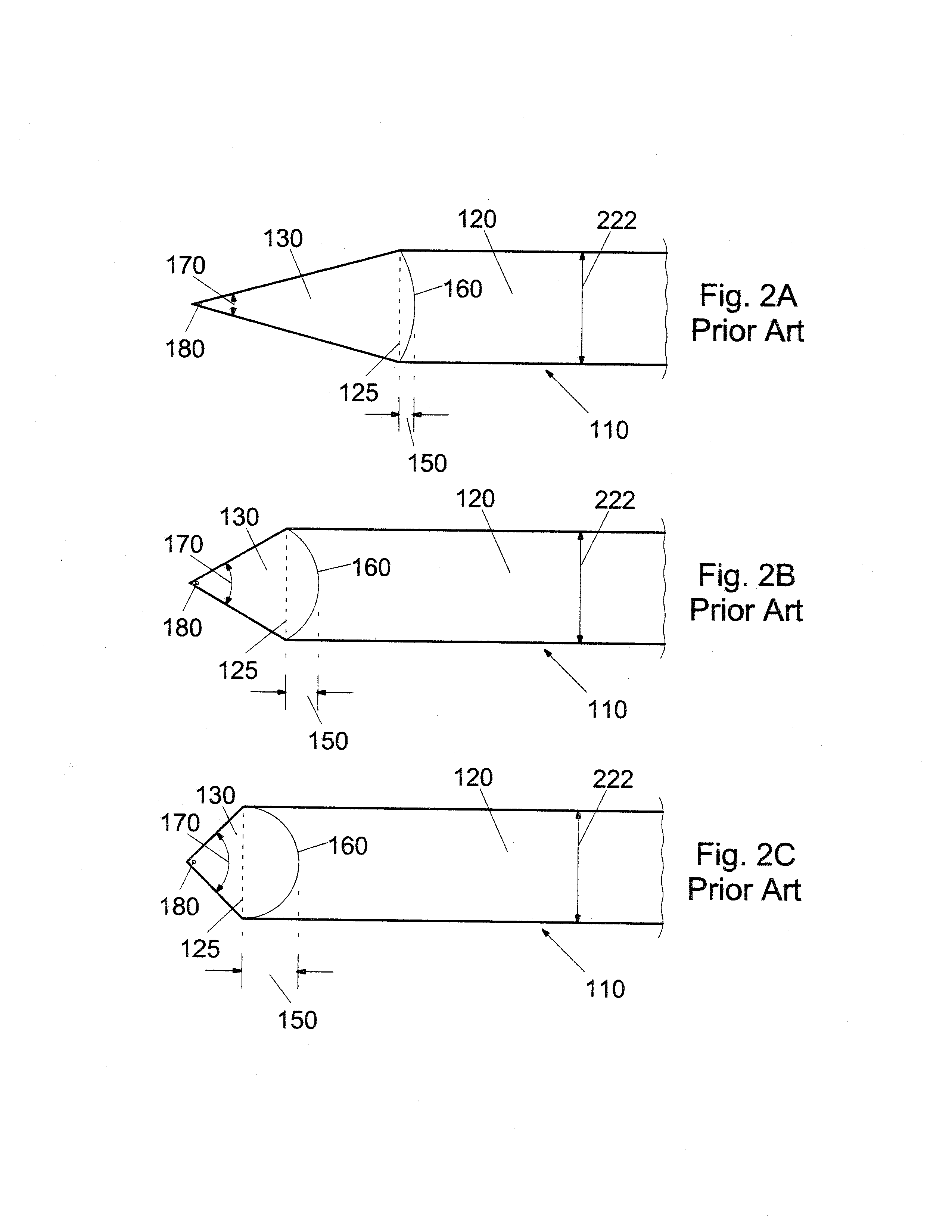
(1986) pointed out that, although reducing the apex angle decreased the end effect, it also unavoidably increased the relative contribution of the “edge effect” to the distortion of the fluid flow profile.
In channels with smaller apex angles, however, images showed significant tailing and departure from simple end effect calculated flow profiles.
The ability to improve separation resolution by simply altering the apex angle therefore appears to be limited by the need to balance the deleterious consequences of the two (end and edge) effects.
These studies by Giddings and Williams clearly show that reducing the apex angle in the transitional triangular section between regions of different cross-sectional areas is not by itself sufficient to eliminate the dispersion and resolution losses brought about by end effects.
As indicated above, improvements in resolution, however, often come with tradeoffs and limitations.
(2006) pointed out that further reduction in band broadening may ultimately be limited by increases in local edge effects that result from the presence of the microstructures.
Both approaches increase the complexity of the flow system and add another challenge to the manufacturing process.
No commercially available flow system or instrument has incorporated either of the volume-reduction approaches.
Electrokinetic techniques, however, also exhibit some significant drawbacks.
Electroosmotic flow is not particularly robust and is highly sensitive to the physicochemical properties of the solution and channel walls.
When used with real samples, care must be taken to insure that solute molecules do not adsorb onto channel walls (often unavoidable and uncontrollable) creating inhomogeneities in surface charge density and local areas of flow anomalies.
The need for an electrically conductive solution with tightly controlled pH and ionic strength generally makes the technique inapplicable to non-aqueous media or the use of solution gradients.
Unfortunately, the composition of the conductive solution can be influenced by the electrochemical reactions at the system's electrodes that are used to maintain the required electric field in solution.
High operating voltages (1-30 kV power supply) resulting in high currents in solution can also bring about runaway Joule heating and the need for cooling.
Because each faceted interface introduces a small amount of dispersion, there is also a practical upper limit to the number of interfaces that can be coupled together.
Using electrokinetic flow alone, it is difficult to extend the methodology for microscale channels to handle macroscale systems.
(2005), however, have found that velocity variations along faceted interfaces using pressure-driven flow can be unacceptable for many applications.
Although novel approaches have been developed to lessen the impact of end effects on band spreading, few of the methods are currently used on a regular basis, and none totally eliminate the problem.
Without a solution, however, high resolution, high throughput separations and transfer processes are difficult to achieve.
The problem, in fact, is becoming even more acute as new preparative scale applications move to wider channels to provide higher load capacity and analytical work trends towards smaller microscale systems to minimize analysis time and the amount of sample and fluid medium required.
Since the relative contribution of end effects to separation inefficiency dramatically increases as the channel becomes either shorter or wider, end effects ultimately limit channel dimensions.

Method used


Image

  • Apparatus and methods for transferring materials between locations possessing different cross-sectional areas with minimal band spreading and dispersion due to unequal path-lengths
  • Apparatus and methods for transferring materials between locations possessing different cross-sectional areas with minimal band spreading and dispersion due to unequal path-lengths
  • Apparatus and methods for transferring materials between locations possessing different cross-sectional areas with minimal band spreading and dispersion due to unequal path-lengths

Examples


Embodiment Construction

[0071]The present invention will now be described more fully hereinafter with reference to the accompanying drawings, in which a preferred embodiment of the invention is shown. This invention may, however, be embodied in many different forms and should not be construed as limited to the embodiment set forth herein. Rather, this embodiment is provided so that this application will be thorough and complete, and will fully convey the true scope of the invention to those skilled in the art. Like numbers refer to like elements throughout the figures.

[0072]The illustrations of the embodiments described herein are intended to provide a general understanding of the structure of the various embodiments. The illustrations are not intended to serve as a complete description of all of the elements and features of apparatus and systems that utilize the structures or methods described herein. Many other embodiments may be apparent to those of skill in the art upon reviewing the disclosure. Other ...


PUM

PropertyMeasurementUnit
widthaaaaaaaaaa
widthaaaaaaaaaa
operating voltagesaaaaaaaaaa

Abstract

Non-limiting exemplary embodiment(s) of apparatus(es) and method(s) are described for the conveyance of fluid media and entrained materials between two or more locations, each possessing a different cross-sectional area. Equidistant pathways incorporated into uniquely designed conduits enable this transference to occur with minimal band spreading and separation resolution loss due to undesirable flow patterns that arise from end effects. The design enables the conduits to be employed with locations of almost any description including process channels, surfaces, or even open volume of any size and used for almost any purpose. The conduits and/or associated locations may be empty of any contents or filled with gelatinous, porous, granular, or particulated material. The design of non-limiting exemplary embodiment(s) of apparatus(es) and method(s) may be easily adapted or configured as necessary.

Description

CROSS REFERENCE TO RELATED APPLICATIONS[0001]Not Applicable.STATEMENT REGARDING FEDERALLY SPONSORED RESEARCH OR DEVELOPMENT[0002]Not Applicable.REFERENCE TO A MICROFICHE APPENDIX[0003]Not Applicable.BACKGROUND OF THE INVENTION[0004]1. Technical Field[0005]This application relates generally to fluid distribution. More specifically, the application provides apparatuses that enable fluid and sample particles to be uniformly distributed and collected to and from process channels, surfaces, or open volumes with minimal dispersion.[0006]2. Prior Art[0007]Many analytical and engineering processes use fluids to transport bands of material or samples between locations. In most, if not all, of these applications, it is important to keep spreading, skewing, and mixing of the bands to a minimum. As the materials move through the fluid handling systems, they can be subjected to dispersion resulting from diffusion, turbulent mixing, and non-uniform flow velocities. Unintended and undesirable hydr...

Claims


Application Information

Patent Timeline
Patent Type & Authority Applications(United States)
IPC IPC(8): B01L3/00G01N1/10
CPCB01L3/5027B01L2200/0636Y10T436/2575B01L2400/0487F16L9/006B01L2300/0874B01L3/502746B01L2400/084Y10T137/85978
Inventor SENFTLEBER, FRED C.
Owner SENFTLEBER FRED C
Why Eureka
Try Eureka