Vehicle operator display and assistive mechanisms

Active Publication Date: 2013-07-18
ENGINEERED ARRESTING SYST CORP
View PDF14 Cites 64 Cited by
  • Summary
  • Abstract
  • Description
  • Claims
  • Application Information

AI Technical Summary

Benefits of technology

[0020]The present invention provides assistive mechanisms designed to reduce risks associated with degraded landing and other situations. Some versions of the invention include a display unit with a visual indicator located above the glare shield or dashboard of a cockpit, cabin, or other area located within the normal field of view of the operator. The invention also may include a distinctive aural alert designed to be easily distinguished from other aural alerts the vehicle may employ for other purposes. A funct

Problems solved by technology

. . the pilots “assumed the runway was in ‘fair’ condition, based on reports from other pilots radioed to them by air traffic controllers.” However, subsequent analysis of objective data “show[ed] the conditions were ‘poor’ at best,” with the runway “so slippery that it would have been difficult for people to walk on, providing minimal traction for the jet's tires as pilots tried to slow down.”
It is essentially impossible for pilots to discriminate between the aerodynamic forces acting upon an aircraft and the ground-based braking forces during a landing.
As a result, the risks associated with poor ground-based braking system performance are not visible to a pilot in the act of directing his aircraft during such a maneuver.
Indeed, while humans are not considered “machines,” they do operate under industry recognized cognitive limitations when in the process of interacting with mechanical devices.
As suggested by the accident at Midway Airport (among other events), unexpected degradation in ground-based deceleration systems can drastically erode safety and lead to catastrophic consequences any time a vehicle is decelerating on a surface while employing both aerodynamic and ground-based deceleration systems.
However, the hum

Method used


Image

  • Vehicle operator display and assistive mechanisms
  • Vehicle operator display and assistive mechanisms
  • Vehicle operator display and assistive mechanisms

Examples


Embodiment Construction

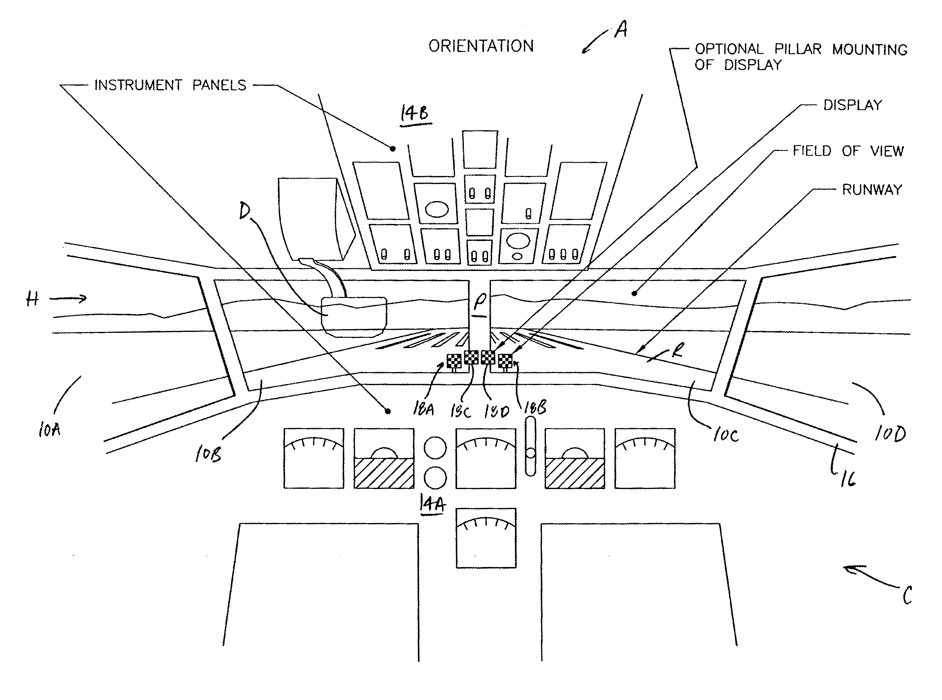
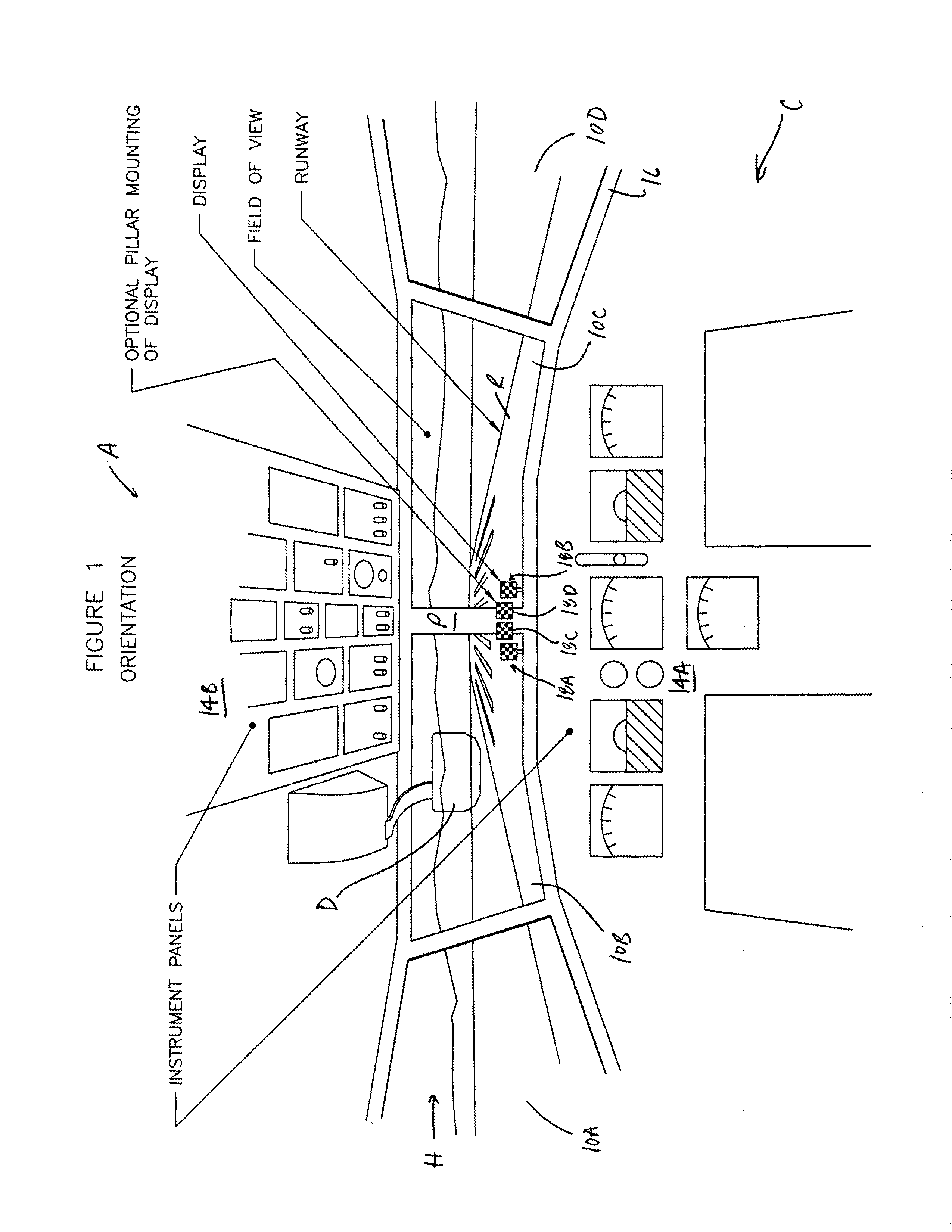
[0035]Depicted in FIG. 1 is a portion of a cockpit C of an exemplary aircraft A. Visible in FIG. 1 within cockpit C are windows 10A-D, panels of instruments 14A-B, main glare shield 16, and one or more alerting devices 18 (see also FIGS. 2-3). Also visible in FIG. 1 outside cockpit C are runway R and horizon H. Although FIG. 1 relates to an aircraft A, it alternatively could show portions of a car, truck, bus, or other ground-based vehicle approaching, for example, a roadway or a boat approaching an area of water.

[0036]As illustrated in FIG. 1, the field of view of a pilot (whether seated to the left or right of the center of cockpit C) of aircraft A includes forward-looking windows 10B-C for visual acquisition of the runway R. Windows 10B-C are the primary visual source for information relating to the operational control of the aircraft A while it is in the process of decelerating. Accordingly, at least one of alerting devices 18A-B preferably is located within the pilot's field of...


PUM


Abstract

Detailed are assistive mechanisms for vehicle operators designed to reduce risks associated with degraded landing and other situations. Some mechanisms may include a display with a visual indicator located within the peripheral field of view of an operator. Aural alerts may also be employed. Information suggesting degradation of, for example, ground deceleration performance may alert the operator to perform unusual or abnormal actions to mitigate hazards produced by the performance degradation.

Description

CROSS-REFERENCE TO RELATED APPLICATIONS[0001]This application claims the benefit of and priority to (1) U.S. Provisional Patent Application Ser. No. 61 / 587,802, filed Jan. 18, 2012, entitled “Display Mechanism for Communicating Transport Vehicle Related Ground Deceleration Alerts to the Operators of an Aircraft or Vehicle for the Purposes of Failure Sensitive Mitigation Actions,” and (2) U.S. Provisional Patent Application No. 61 / 679,879, filed Aug. 6, 2012, entitled “Vehicle Operator Display and Assistive Mechanisms,” the entire contents of both of which are incorporated herein by this reference.FIELD OF THE INVENTION[0002]This invention relates to systems and methods for providing information to (at least) vehicle operators and more particularly, but not necessarily exclusively, to mechanisms and techniques for supplying human pilots with information in manners designed to assist the pilots in coping with probable degradation of ground deceleration performance of their associated ...

Claims


Application Information

Patent Timeline
IPC IPC(8): G06F19/00
CPCG01C23/005G08G5/0021G01C23/00B60T8/1703
Inventor GADZINSKI, JOHN
Owner ENGINEERED ARRESTING SYST CORP
Why Eureka
Try Eureka