Hinge structure for assembly of a display module

Inactive Publication Date: 2013-07-25
SINHER TECH INC
View PDF37 Cites 3 Cited by
  • Summary
  • Abstract
  • Description
  • Claims
  • Application Information

AI Technical Summary

Benefits of technology

[0004]The primary object of the present invention is to solve the problems of the conventional LED panel that is too thin and can be fastened only at the front side

Problems solved by technology

However, the lateral sides of the LED panel usually do not have a sufficient thickness for fastening of the side legs.
But such a fastening approach makes production process more difficult, and a front lid and a rear lid are required to e

Method used


Image

  • Hinge structure for assembly of a display module
  • Hinge structure for assembly of a display module
  • Hinge structure for assembly of a display module

Examples


Embodiment Construction

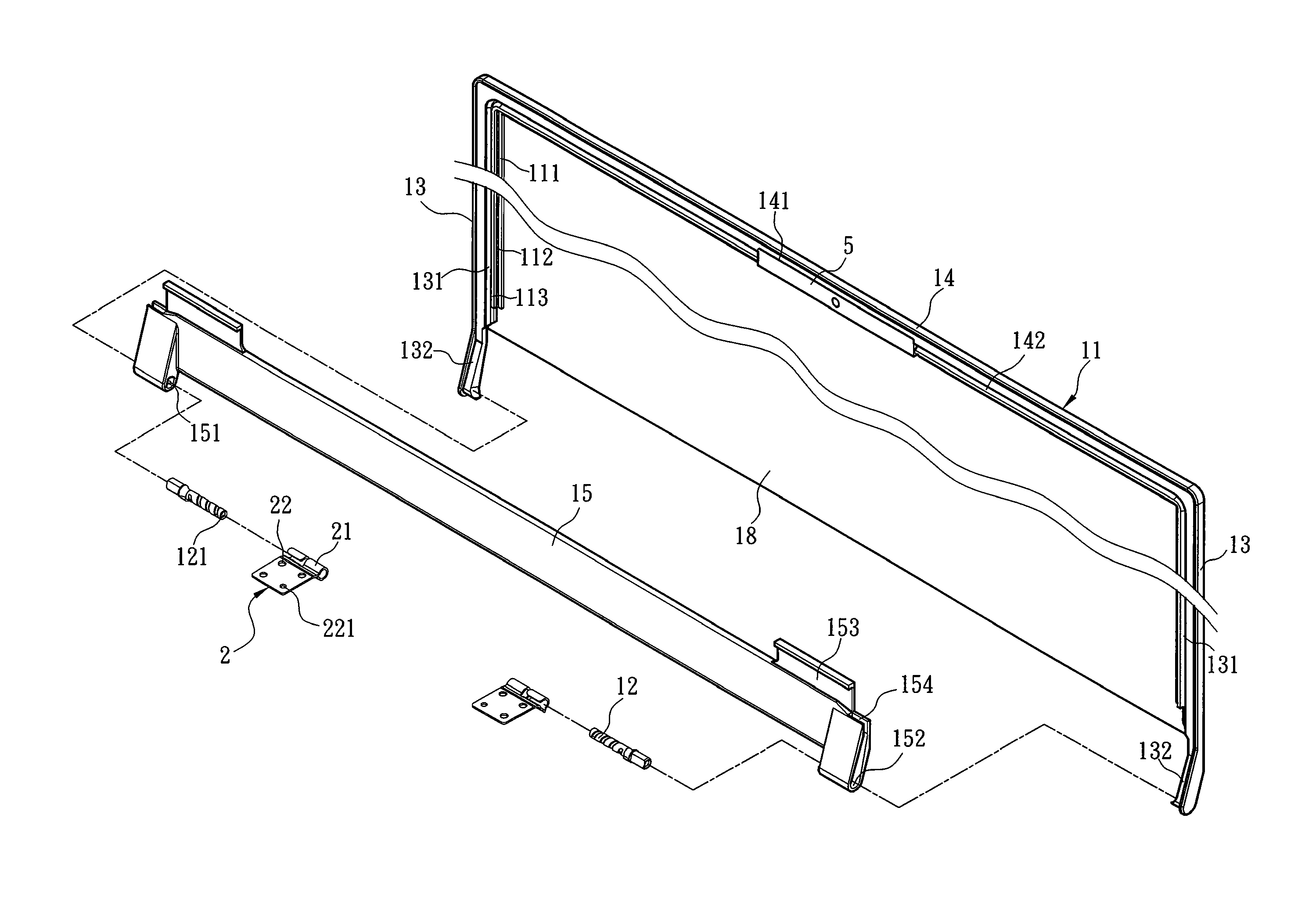
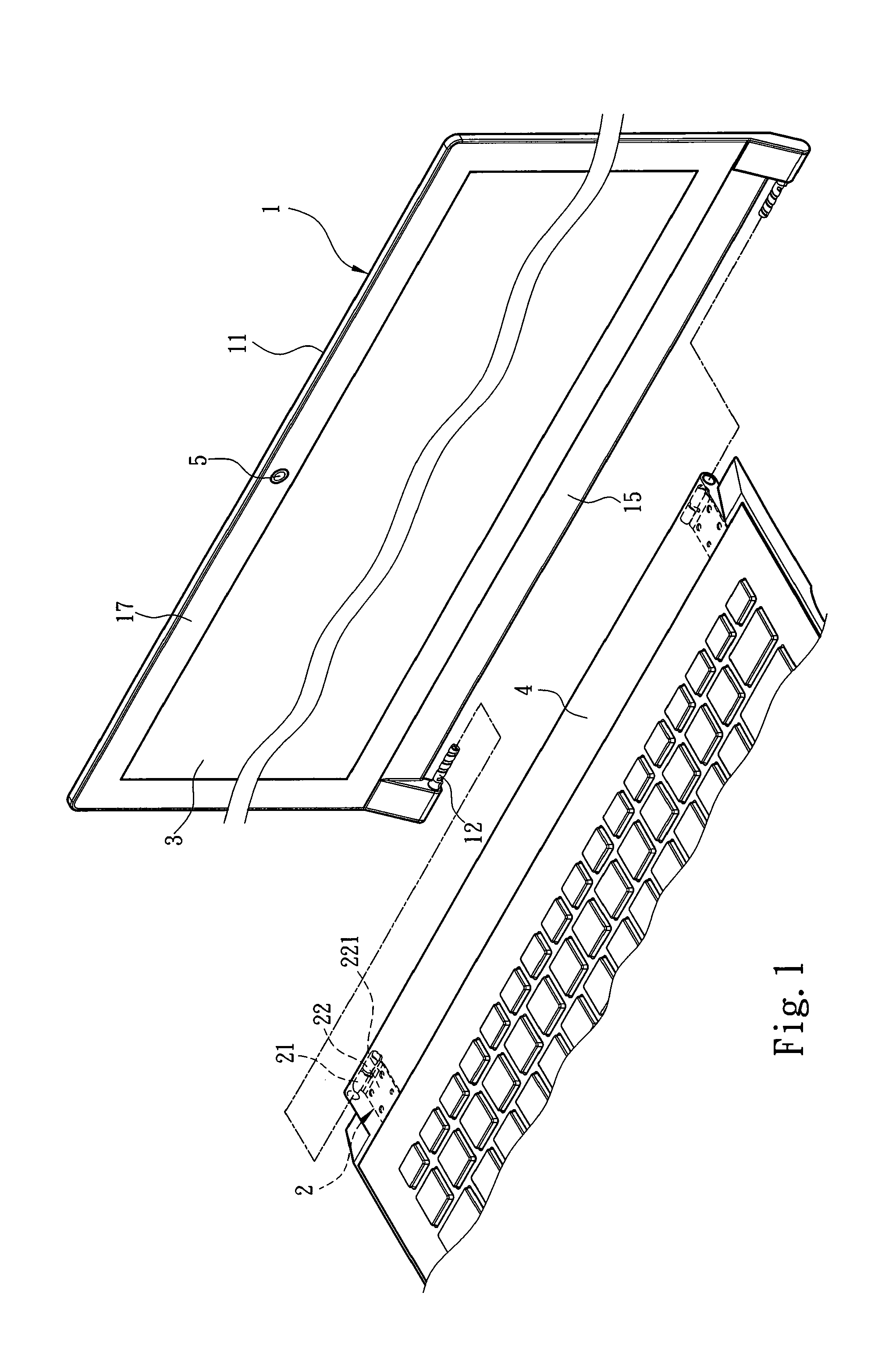
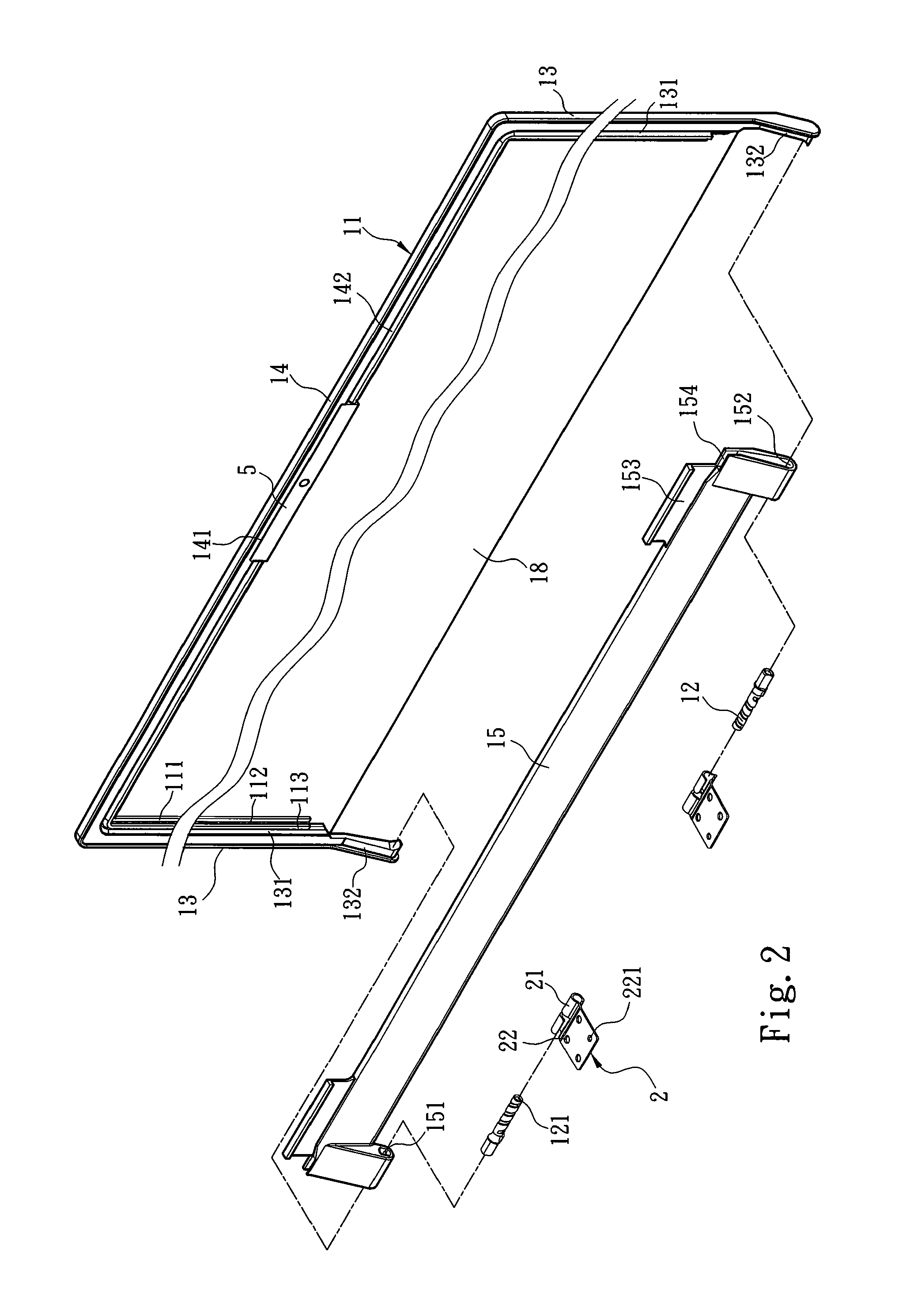
[0032]Please referring to FIGS. 1 and 2, the present invention aims to provide a hinge structure for assembly of a display module. It is located on a base 4. In this embodiment, the base 4 is a host of a notebook computer that can include an electronic device (not shown in the drawings) consisting of a processing unit, a keyboard module, a storage device, a wireless terminal module or an optical read / write device and the like. The hinge structure for assembly of a display module includes a first holder 1 and a second holder 2. The first holder 1 includes an assembly portion 11 and at least one pin 12 coupled with the assembly portion 11. The assembly portion 11 has two parallel extension racks 13 coupled with the pin 12, a top rack 14 located between the two extension racks 13 and a bottom rack 15. The top rack 14 includes a retaining groove 141 to hold a video device 5 and two ends fastened integrally to the two extension racks 13. The bottom rack 15 has two fastening portions 151 ...


PUM


Abstract

A hinge structure for assembly of a display module is located on a base. The hinge structure includes a first holder and a second holder. The first holder includes an assembly portion and at least one pin coupled with the assembly portion. The second holder includes a hinge portion hinged on the pin and a connecting portion fastened to a host of a notebook computer. The display module is located in a first holding groove and a second holding groove of the assembly portion, thereby the hinge structure and display module are fastened together to reduce thickness caused by front fastening to achieve the object of thin and light panel design. By direct coupling of the display module and the assembly portion the extra production process of fastening the hinge to the display module can be dispensed with to simplify production.

Description

FIELD OF THE INVENTION[0001]The present invention relates to a hinge structure and particularly to a hinge structure for assembly of a display module.BACKGROUND OF THE INVENTION[0002]Earlier CCFL (Cold Cathode Fluorescent Lamp) consists of a backlight module (cold cathode ray tube) and a liquid crystal light interrupter. The liquid crystal light interrupter consists of a polarizer, a glass substrate, a transparent electrode and a liquid crystal layer. As a result, the CCFL panel has a substantial thickness. In the past fastening the CCFL panel relies on two side legs to hold the liquid crystal screen. The lateral sides of the liquid crystal panel are fastened to the side legs, then are hinged on the host of a notebook computer. To meet the requirements of long use time of the notebook computer and thin and light product design, the earlier CCFL panel is gradually being replaced by LED panel. However, the lateral sides of the LED panel usually do not have a sufficient thickness for f...

Claims


Application Information

Patent Timeline
IPC IPC(8): H05K7/00E05D11/00
CPCG06F1/1681Y10T16/553Y10T16/533
Inventor SULIN, WEN YAN
Owner SINHER TECH INC
Why Eureka
Try Eureka