Cable retainer

Inactive Publication Date: 2013-07-25
AIRBUS OPERATIONS LTD
View PDF15 Cites 29 Cited by
  • Summary
  • Abstract
  • Description
  • Claims
  • Application Information

AI Technical Summary

Benefits of technology

The invention is a clamp that can securely hold multiple electrical conductors in an aircraft bundle. The clamp has two parts that can be opened and closed with one hand, making it easy for a fitter to use. The parts are connected by a connection that allows for easy access to the conductor space while still maintaining the clamp as a single object. The first part of the clamp has a recess that can hold a projection on a cable retaining device, ensuring minimal movement between the two parts. Overall, this clamp design simplifies the process of installing and securing electrical conductors in an aircraft bundle.

Problems solved by technology

It only has seven conductor spaces, so it is not well-suited for use with cables which have a neutral conductor in addition to the six phase conductors and the exciter cable.
Installing a cable using such an auxiliary retainer is particularly difficult, however, since the fitter must maintain the main device and auxiliary retainer in the correct position relative to each other whilst fitting a band around both.
It has been found that using this system often results in damage to the device and / or the auxiliary retainer during installation.
Installation of the U.S. '138 device can also be challenging for the fitter because the device has two separate parts.
It is easy during this process for the fitter to drop the second half of the device, or to be too forceful in pushing the conductors into place, either of which can damage the device.
This risk is exacerbated by the fact that the conductors are usually very stiff, whereas certain parts of the device, such as the peripheral arms, are relatively thin and fragile.
The band of a P-clip defines a teardrop shape rather than a circle, meaning that if a P-clip is used to secure the device shown in FIGS. 1a and 1b there will be gaps 9 between the device and the clip at the point of the teardrop as shown in FIG. 1a. It has been found that conductors can escape from the peripheral spaces into these gaps, leading to electromagnetic interference between the phases.
Furthermore, the gaps 9 mean that the P-clip band does not fully engage with the circumferential channel on the device so in use the P-clip can become laterally dislodged from the device.
In other locations in an aircraft it may not be possible to use P-clips to attach a cable bundle to the aircraft structure because of space constraints.
As is clear from FIG. 1b, prior art saddle clamps are configured for attachment to surfaces which are perpendicular to the longitudinal axis of the cable bundle, and this limits the situations in which they can readily be used.
It also means that they are quite bulky, and that the cable bundle cannot be held closely against a surface which it runs parallel to by such saddle clamps.

Method used


Image

  • Cable retainer
  • Cable retainer
  • Cable retainer

Examples


Embodiment Construction

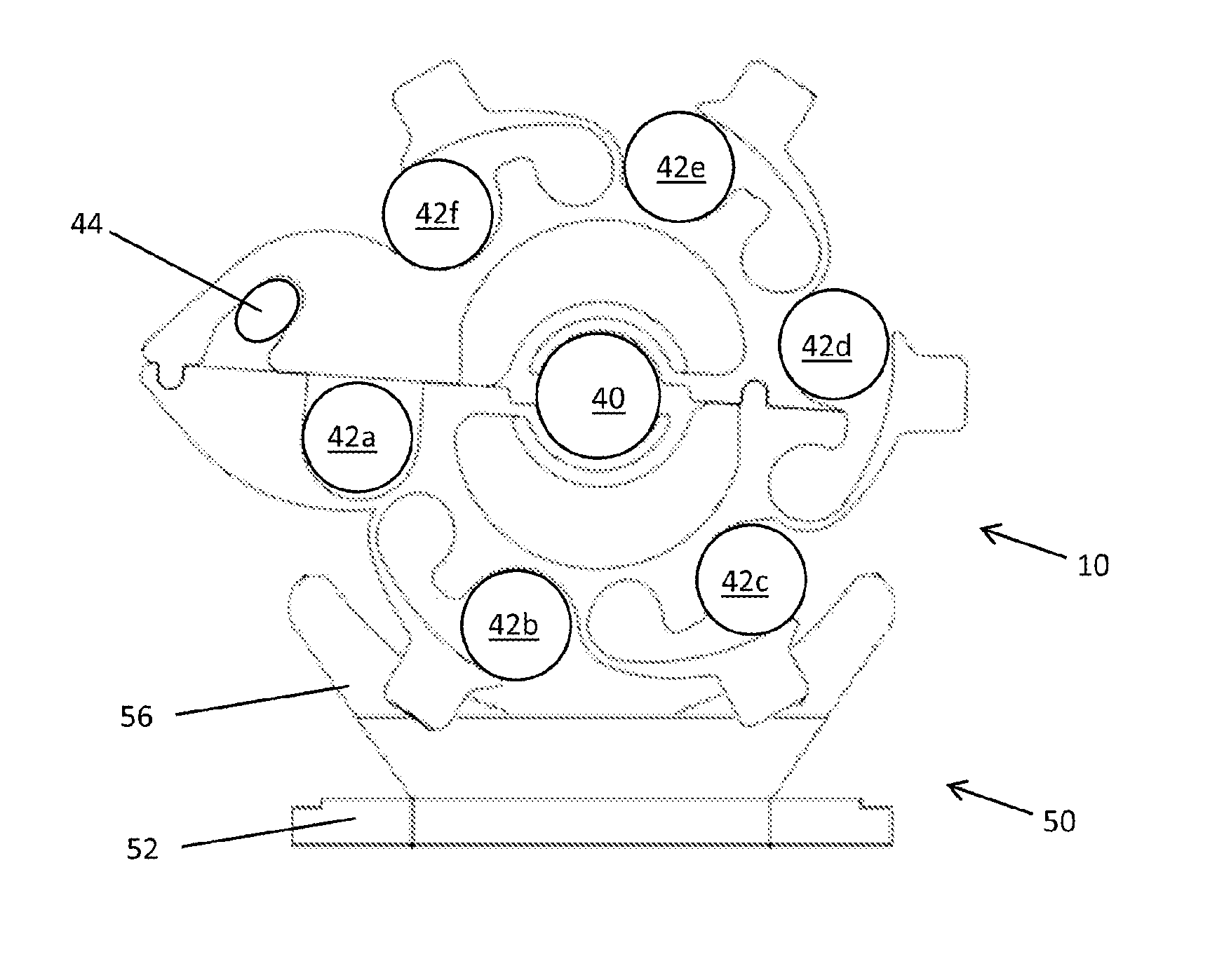
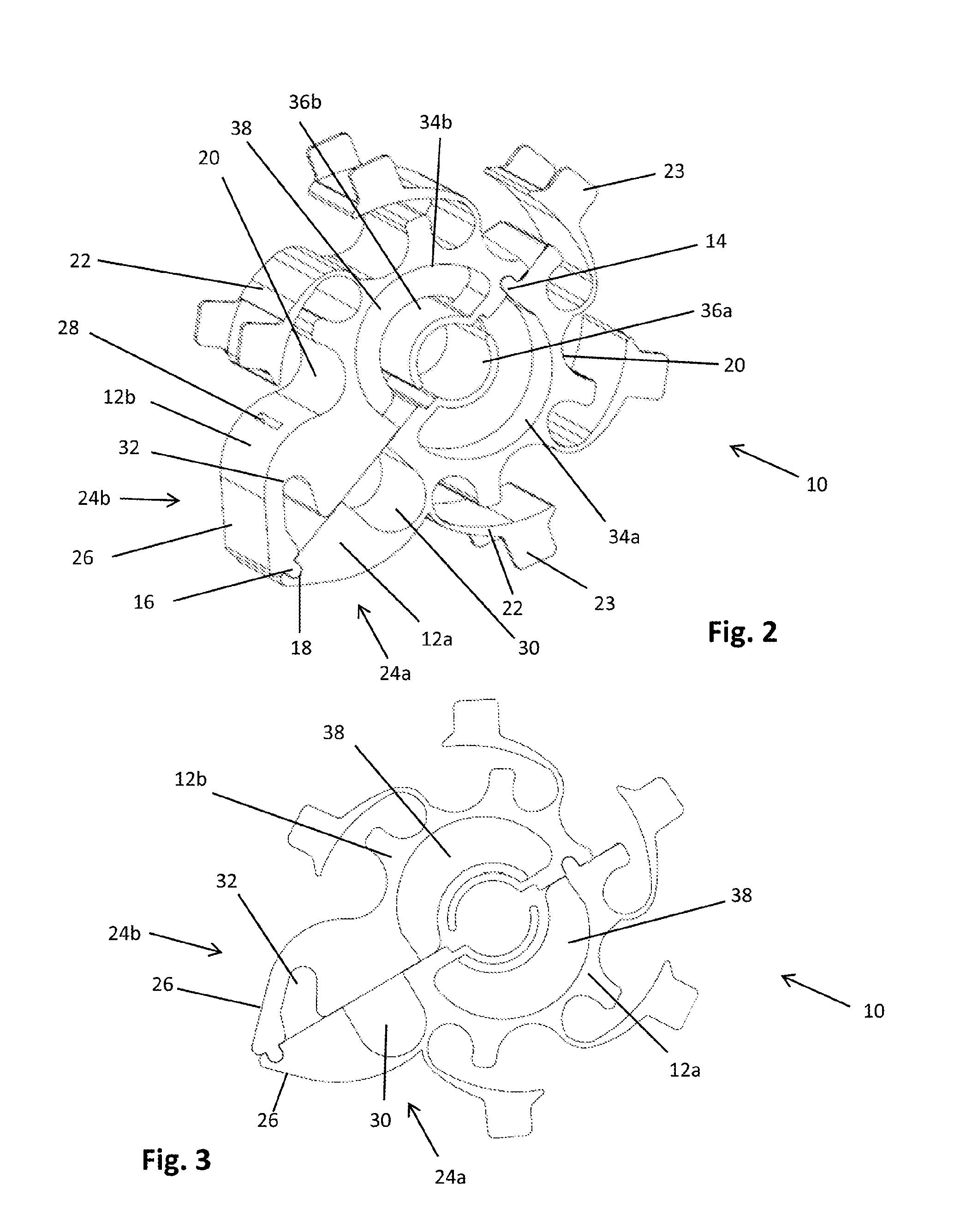
[0079]FIGS. 2 and 3 show a cable retaining device 10 according to an example embodiment of the invention. The device 10 comprises two sections 12a and 12b moulded from a plastics material such as polyetherimide. If resistance to very high temperatures is required then the plastics material can be reinforced with glass fibres. The overall thickness of the device is 20 mm. When in the closed configuration shown in FIGS. 2 and 3 the device has a maximum dimension in the plane of 60 mm.

[0080]Sections 12a and 12b are connected by a hinge 14. Hinge 14 consists of two pins formed integrally with section 12a, which locate with either end of a cylindrical bore in section 12b, such that the sections may pivot relative to each other about the pins between an open configuration (not shown) and the closed configuration shown in FIGS. 2 and 3. Section 12b includes a projection 16 at the opposite end of the device to hinge 14, which snap-fits into a corresponding recess 18 on section 12a to hold t...


PUM

PropertyMeasurementUnit
Angleaaaaaaaaaa

Abstract

A device and method for securing a plurality of electrical conductors in a bundle. The device (10) comprises first and second portions (12a, 12b) connected so as to be moveable between a closed configuration in which the first and second portions define at least one enclosed space which extends through the device and an open configuration in which a conductor may be moved laterally into the at least one space from the periphery of the device. The device further includes a plurality of recesses (20) for receiving conductors disposed around its peripheral edge.

Description

FIELD OF THE INVENTION[0001]The present invention concerns a device for securing cables. More particularly, but not exclusively, this invention concerns a device for securing a plurality of electrical conductors in a bundle, and a method of securing together conductors in an aircraft. The invention also concerns a clamp for attaching a bundle of conductors held together by a cable retaining device to a surface.BACKGROUND OF THE INVENTION[0002]In an aircraft, cables made up of bundles of electrical conductors are used to distribute power from an electrical generator to various items of equipment which require electrical power to operate. Such cables usually carry three phases, with each phase being associated with two individual conductors connected in parallel. Thus, the cable is a bundle of six individual electrical conductors. An exciter cable which supplies field energy and control signals to the electrical generator is also often routed together with the power cable. The power c...

Claims


Application Information

Patent Timeline
IPC IPC(8): H02G3/02H02G1/00
CPCH02G3/32H02G1/00Y10T29/49826Y10T24/14H02G3/02
Inventor BLAKELEY, LAWRENCERUIZ DE PABLO, JAVIERO'SHAUGHNESSY, PAULMCLLVEEN, MARK
Owner AIRBUS OPERATIONS LTD
Why Eureka
Try Eureka