
Long Decay Phosphors for Lighting Applications

Active Publication Date: 2013-07-25
INTEMATIX
View PDF6 Cites 14 Cited by
  • Summary
  • Abstract
  • Description
  • Claims
  • Application Information

AI Technical Summary

Benefits of technology

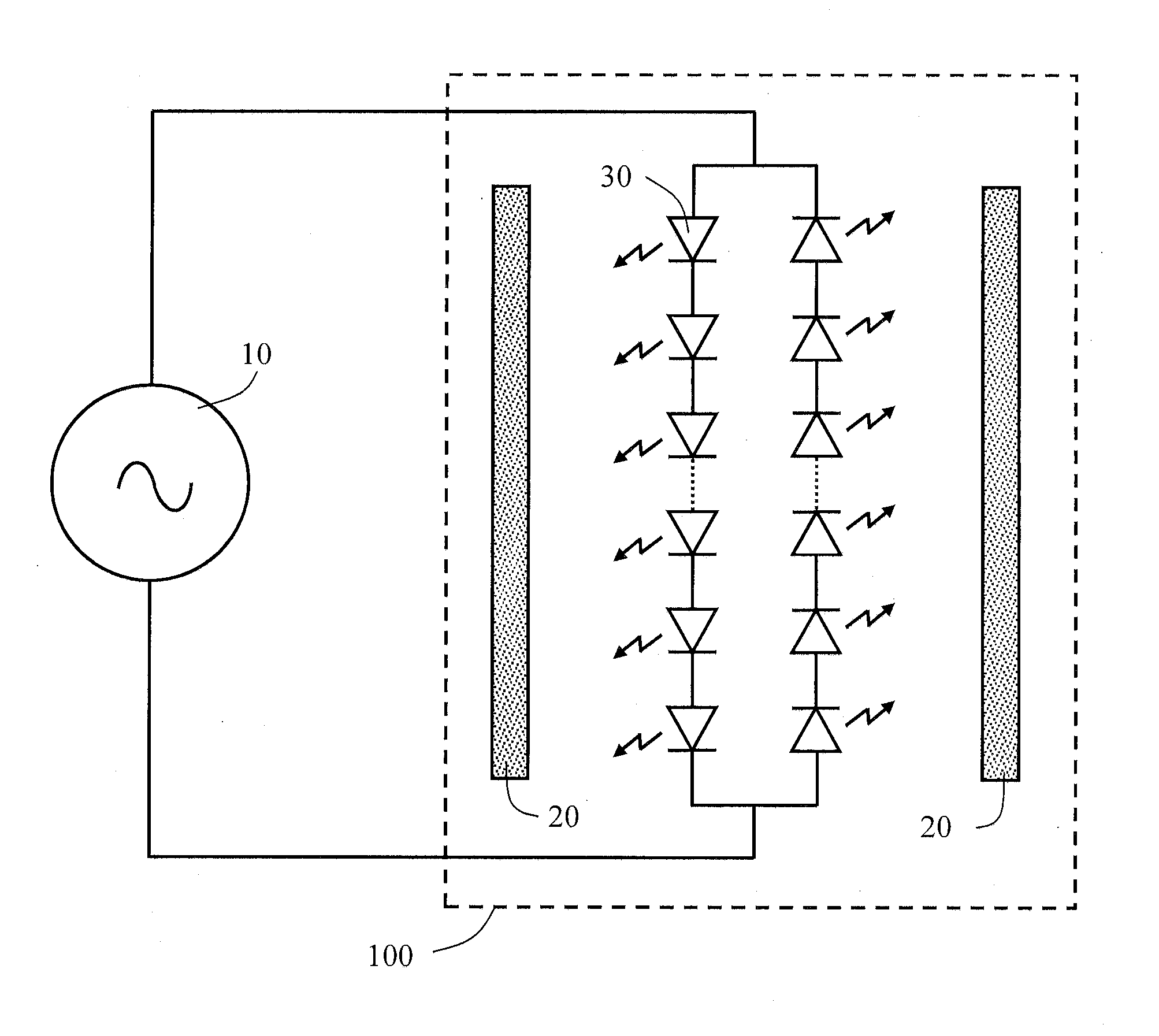
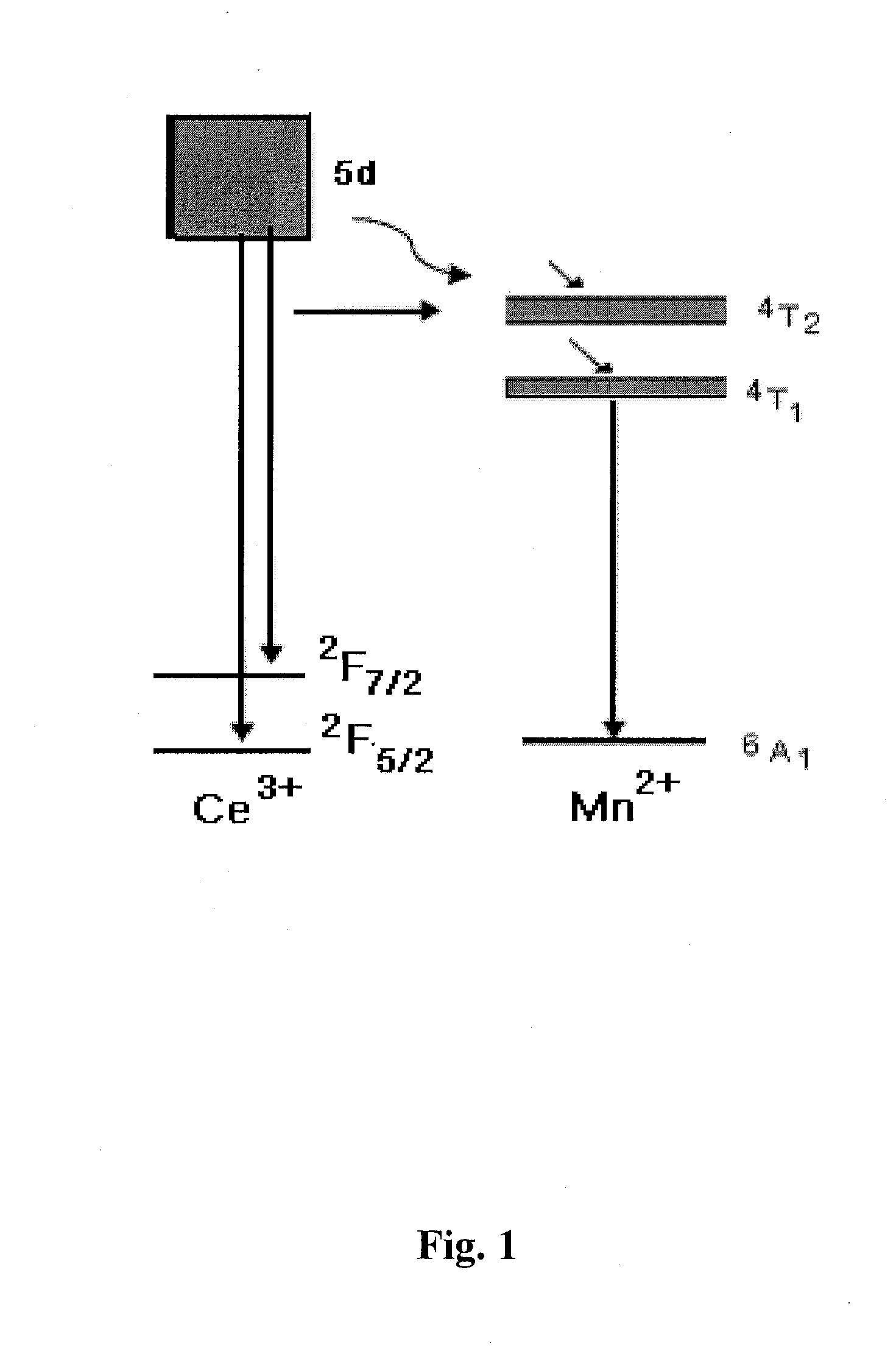
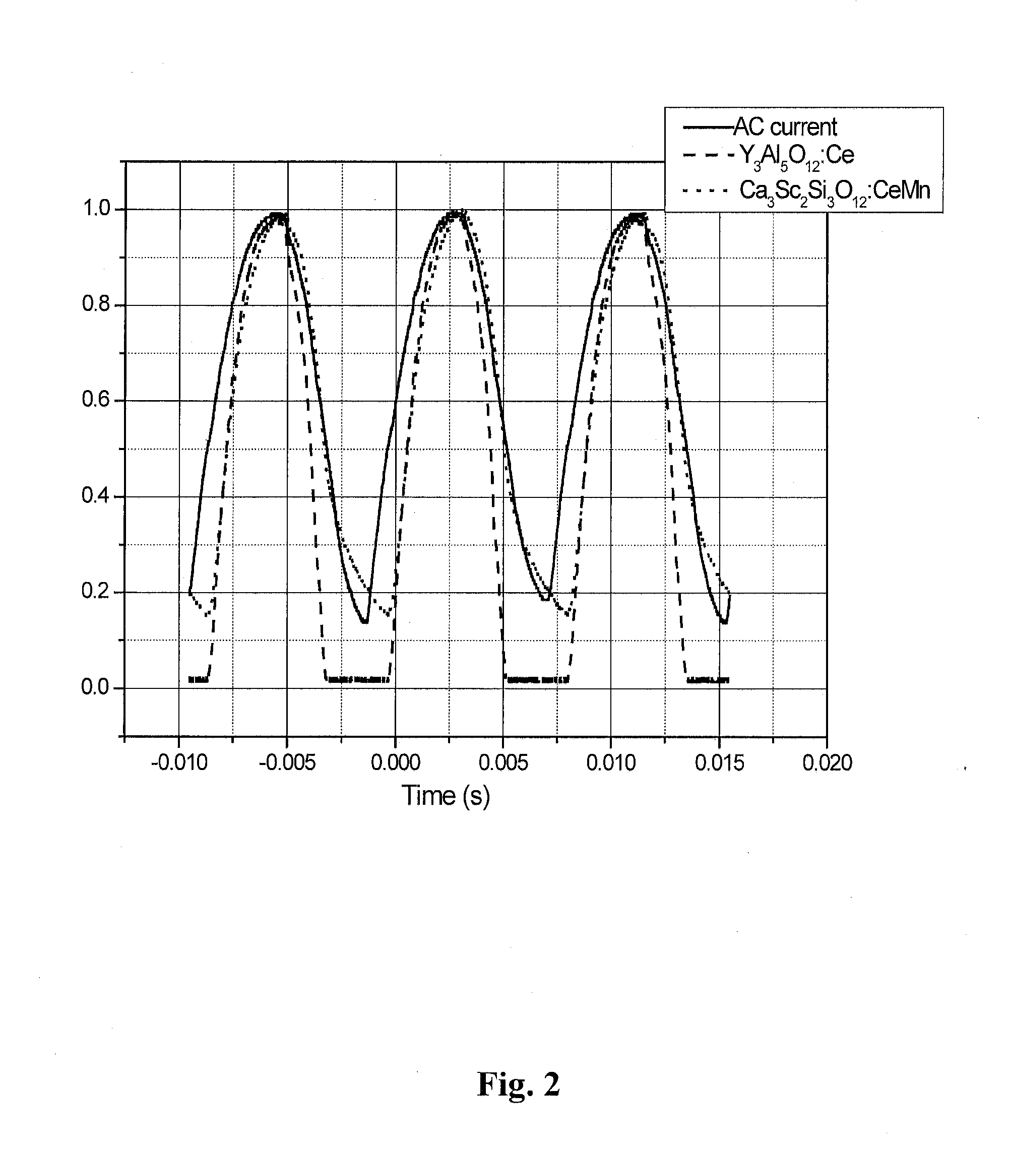
The patent describes an improved photoluminescent material that has a long decay time, meaning it emits light for a longer period of time after being excited. This material is based on a cerium-doped calcium scandium silicate phosphor that is co-doped with Mn2+ to increase the decay time. The material can be used in AC LED lighting systems and has good reliability and high quenching temperature. The long decay time allows for a continuous supply of light, reducing flickering in the output of the device. The material can also produce light during periods of the AC cycle when the excitation source is not generating excitation light. Overall, this patent provides a technical solution for improving the performance of photoluminescent materials in lighting applications.

Problems solved by technology

Furthermore, the photoluminescent material may have a decay time that is configured to reduce flickering in the output of the device.

Method used


Image

  • Long Decay Phosphors for Lighting Applications
  • Long Decay Phosphors for Lighting Applications
  • Long Decay Phosphors for Lighting Applications

Examples


Embodiment Construction

[0034]Embodiments of the present invention will now be described in detail with reference to the drawings, which are provided as illustrative examples of the invention so as to enable those skilled in the art to practice the invention. Notably, the figures and examples below are not meant to limit the scope of the present invention to a single embodiment, but other embodiments are possible by way of interchange of some or all of the described or illustrated elements. Moreover, where certain elements of the present invention can be partially or fully implemented using known components, only those portions of such known components that are necessary for an understanding of the present invention will be described, and detailed descriptions of other portions of such known components will be omitted so as not to obscure the invention. In the present specification, an embodiment showing a singular component should not be considered limiting; rather, the invention is intended to encompass ...


PUM

PropertyMeasurementUnit
Fractionaaaaaaaaaa
Fractionaaaaaaaaaa
Timeaaaaaaaaaa

Abstract

A photoluminescent material has the characteristic of a long photoluminescence decay and has the general composition Ca3-x-m-nAxSc2-yMySi3-zEzO12:mCe3+,nMn2+, where A is at least one divalent cation including Sr, Ba or a combination of monovalent and trivalent cations including combinations of Li, Na, K, B, Al and Ga; M is at least one trivalent cation including Al, Ga, or a divalent cation including Mg, E is a combination of a trivalent and a pentavalent cation including B, Al, Ga, N and P, or a combination of monovalent and trivalent cations including Li, Na, K, B, Al, Ga, N and P. The A cation replaces Ca; the M cation replaces Sc, and E replaces Si. This Mn and Ce doped phosphor emits in the yellow to green with a peak at around 510 and / or 560 and 690 nm. The phosphor material has applications in LED illumination systems.

Description

CROSS-REFERENCE TO RELATED APPLICATIONS[0001]This application claims the benefit of U.S. Provisional Application No. 61 / 590,801 filed Jan. 25, 2012, incorporated by reference in its entirety herein.FIELD OF THE INVENTION[0002]Embodiments of the present invention relate to phosphor compositions emitting green to yellow light, wherein the emitted light has a millisecond decay time; moreover embodiments of the invention relate to AC operable white light emitting devices and lighting systems utilizing such phosphors.BACKGROUND OF THE INVENTION[0003]Wavelength conversion methods that use excitation light produced by solid-state light source such as laser diodes (LDs) or light emitting diodes (LEDs) and photoluminescent wavelength conversion materials such as phosphors or quantum dots can produce high brightness light at wavelengths different from the wavelength of the excitation light. In conventional devices, excitation light impinges on a wavelength conversion material, which absorbs t...

Claims


Application Information

Patent Timeline
IPC IPC(8): H05B33/12C09K11/77H05B44/00
CPCH05B33/12C09K11/7721H01L33/502F21V3/0481H05B33/08F21Y2101/02F21Y2115/10F21V3/12H05B45/00H05B45/325C09K11/77212C09K11/77214H05B45/59
Inventor ZENG, QINGHUAWANG, GANGLI, YI-QUN
Owner INTEMATIX
Learn More