Charging/discharging monitoring device and battery pack

a monitoring device and battery pack technology, applied in the direction of electrochemical generators, instruments, transportation and packaging, etc., can solve the problems of difficulty in extension of transmission distance between the devices, direct affect of the destruction of one device (ic) and the destruction of the other device (ic) to be destroyed, etc., to achieve the effect of causing resonan

Inactive Publication Date: 2013-07-25
HITACHI ULSI SYST CO LTD
View PDF0 Cites 33 Cited by
  • Summary
  • Abstract
  • Description
  • Claims
  • Application Information

AI Technical Summary

Benefits of technology

[0019]And, on the respective circuit units, a wire length of each wiring part, in which the respective wiring part connects the capacitor with the corresponding internal connection terminal, is configured to have such a length as to hinder resonance from being caused against electromagnetic wave noises in an electromagnetic wave noise environment under which the circuit unit is arranged.

Problems solved by technology

In such a daisy-chain transmission between the upstream and the downstream, devices are not insulated from each other in direct current, and therefore, this includes a risk that destruction of one device (IC) directly affects the other device (IC) to be destroyed.
Also, this includes such a problem that a transmission line between devices is as an antenna to be affected by exogenous electromagnetic-wave noises, which results in a malfunction and difficulty of extension of a transmission distance between the devices.

Method used


Image

  • Charging/discharging monitoring device and battery pack
  • Charging/discharging monitoring device and battery pack
  • Charging/discharging monitoring device and battery pack

Examples


first embodiment

[0052]A first embodiment to which a charging / discharging monitoring device of the present invention is applied will be explained with reference to FIGS. 1 to 11.

[0053]

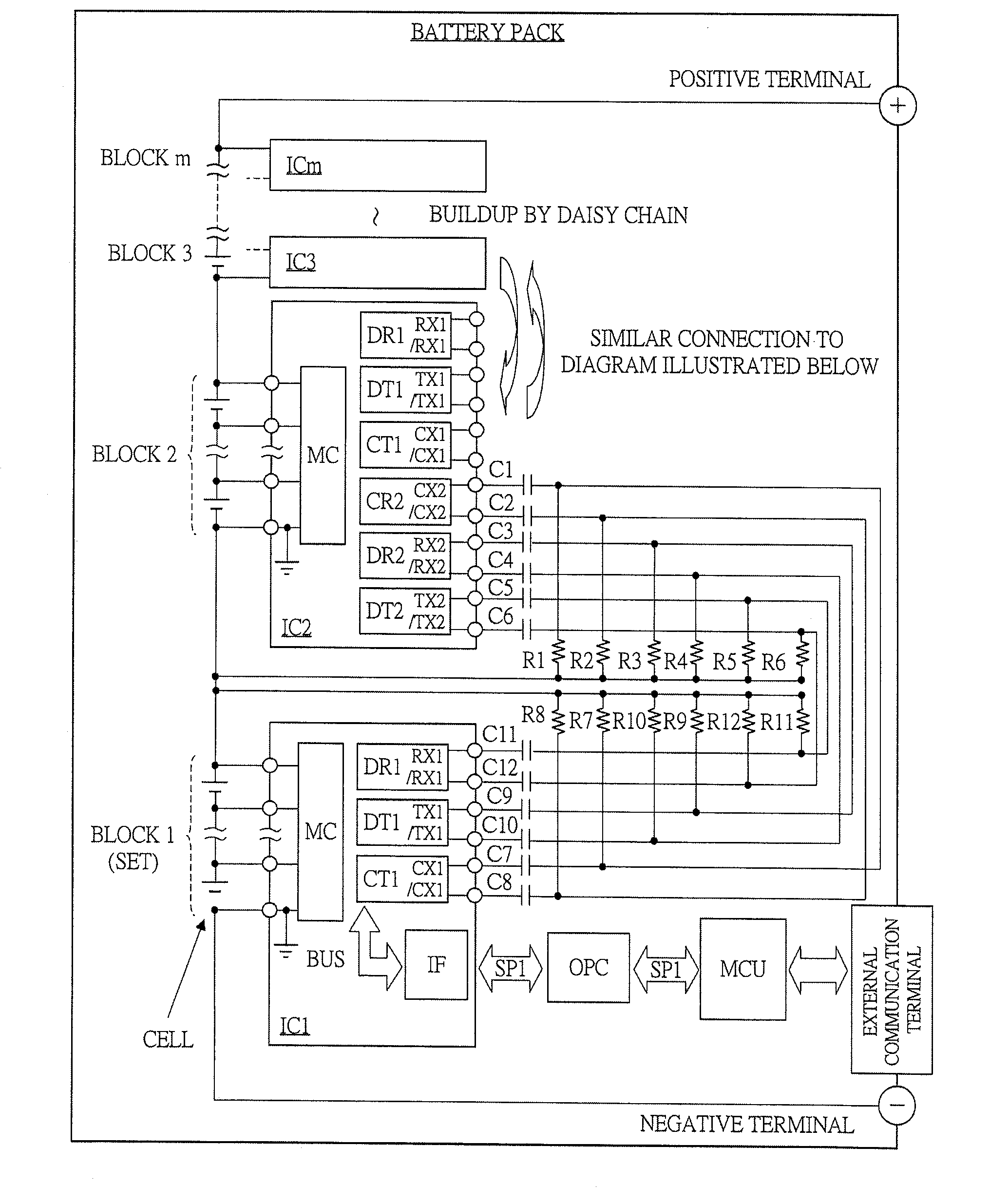
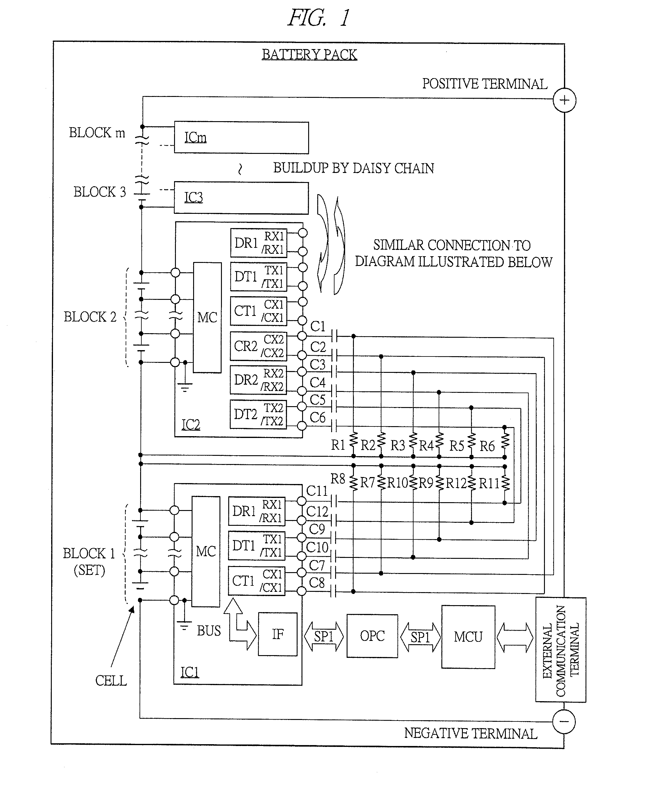
[0054]FIG. 1 illustrates a schematic block diagram of an embodiment of a battery pack to which a charging / discharging monitoring device of the present invention is applied. A plurality of battery cells are connected in a series format between a positive terminal “+” of the battery pack and a negative terminal “−” thereof. Although not particularly limited, each of the above-described plurality of battery cells is of a lithium-ion secondary battery cell. In the plurality of lithium-ion batteries in the series configuration, a plurality thereof form one block (set), and such “m” blocks as a block 1 to a block “m” are formed. As illustrated in, for example, FIG. 2 described later, one block is formed of 12 battery cells.

[0055]When the battery pack of the present embodiment is used for driving a motor of an electric vehicl...

second embodiment

[0115]A second embodiment to which the charging / discharging monitoring device of the present invention is applied will be explained with reference to FIGS. 12 to 26. The present embodiment is a more preferable embodiment with the above-described first embodiment as a basic configuration, and will be explained sequentially based on each drawing.

[0116]

[0117]FIG. 12 illustrates a schematic block diagram of a configuration of a resistive connection in 2-series capacitive coupling of a more preferable embodiment of the battery pack to which the charging / discharging monitoring device of the present invention is applied. FIG. 12 illustrates an example of a secondary battery module MD2 and a secondary battery module MD3 (secondary battery modules MD4 to MDm are also the same). Also, the data transmission circuit DT and the data reception circuit DR are configured as one data transmission / reception circuit DTR, and besides, the clock transmission circuit CT and the clock reception circuit CR...


PUM


Abstract

A charging/discharging monitoring device of a battery pack, includes: a plurality of monitoring integrated circuits; a plurality of wiring boards on which the plurality of monitoring integrated circuits are mounted, respectively; and a plurality of signal transmission paths for, via corresponded respective capacitors, connecting between the plurality of wiring boards. The charging/discharging monitoring device is configured with a two-wire transmission path for connecting between terminals of an upstream-side monitoring integrated circuit of daisy chain connection and a downstream-side monitoring integrated circuit thereof, and a wire length of a wiring part which connects between the respective capacitors and terminals of the corresponding monitoring integrated circuits on the wiring boards is a length in which resonance is not caused by the electromagnetic wave noises in an electromagnetic wave noise environment under which the wiring boards are arranged.

Description

CROSS-REFERENCE TO RELATED APPLICATION[0001]The present application claims priority from Japanese Patent Application No. 2012-013072 filed on Jan. 25, 2012, the content of which is hereby incorporated by reference into this application.TECHNICAL FIELD OF THE INVENTION[0002]The present invention relates to a charging / discharging monitoring device. For example, the present invention relates to a technology effectively applicable to one in which a signal is transmitted between paired semiconductor integrated circuit units each connected to a different reference potential or driving potential from the other, such as a charging / discharging monitoring device for a battery pack formed by connecting a plurality of secondary or rechargeable battery cells in series in multistage.BACKGROUND OF THE INVENTION[0003]For example, Patent Document 1 (Japanese Patent Application Laid-Open Publication No. 2010-63334) discloses a charge state control device of an assembled battery for solving a variatio...

Claims


Application Information

Patent Timeline
Patent Type & Authority Applications(United States)
IPC IPC(8): H02J7/00H02J7/02
CPCH02J7/00H02J2007/005H02J7/0047H02J7/0048Y02E60/10H01M10/48G01R31/3644G01R31/396G01R31/3835
Inventor HAYASHI, HIROKATSUKATO, HIROYUKIAOYAGI, HIDETOMOENDO, HITOSHI
Owner HITACHI ULSI SYST CO LTD
Why Eureka
Try Eureka