IR microscope with image field curvature compensation, in particular with additional illumination optimization

a technology of image field curvature and compensation, applied in the field of infrared microscopes, can solve the problems of sample image, chromatic aberration, and inability to achieve ir light, and achieve the effect of avoiding chromatic aberration and simple image using the lens system

Active Publication Date: 2013-07-25
BRUKER OPTICS GMBH & CO KG
View PDF8 Cites 12 Cited by
  • Summary
  • Abstract
  • Description
  • Claims
  • Application Information

AI Technical Summary

Benefits of technology

[0025]An embodiment is preferred in which a lens system, in particular comprising two achromatic lenses, is provided to image the second intermediate focus onto the flat viewing surface. Imaging using the lens system is especially simple, in particular as compared with reflecting optical systems. With the achromatic lenses, a chromatic aberration can be avoided.
[0026]In a further, preferred embodiment, a variable aperture for IR l

Problems solved by technology

Imaging of the sample, which should be performed in the same manner in the beam path for visible light and in the beam path for IR light, cannot be achieved with conventional lenses because of their diffe

Method used


Image

  • IR microscope with image field curvature compensation, in particular with additional illumination optimization
  • IR microscope with image field curvature compensation, in particular with additional illumination optimization
  • IR microscope with image field curvature compensation, in particular with additional illumination optimization

Examples


Embodiment Construction

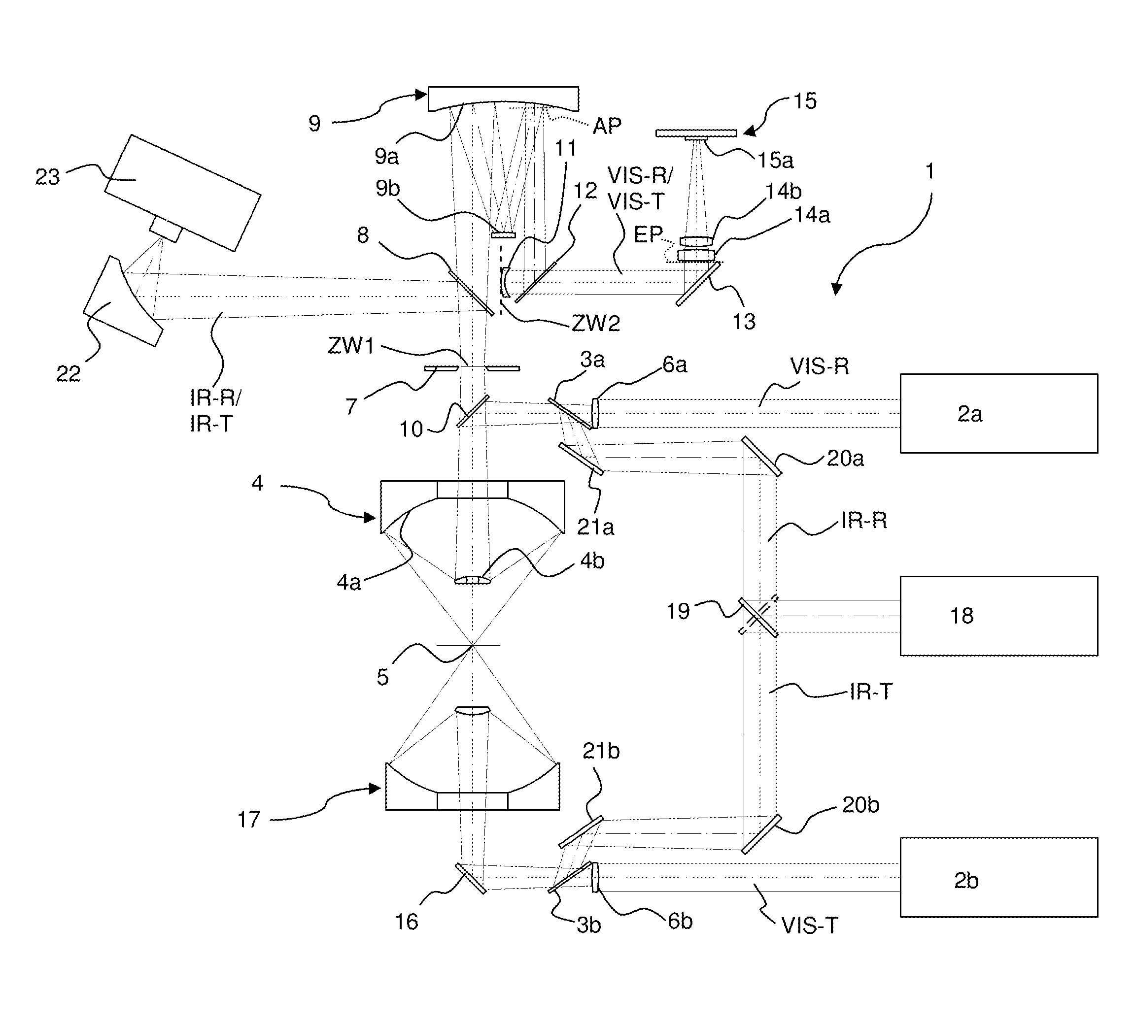
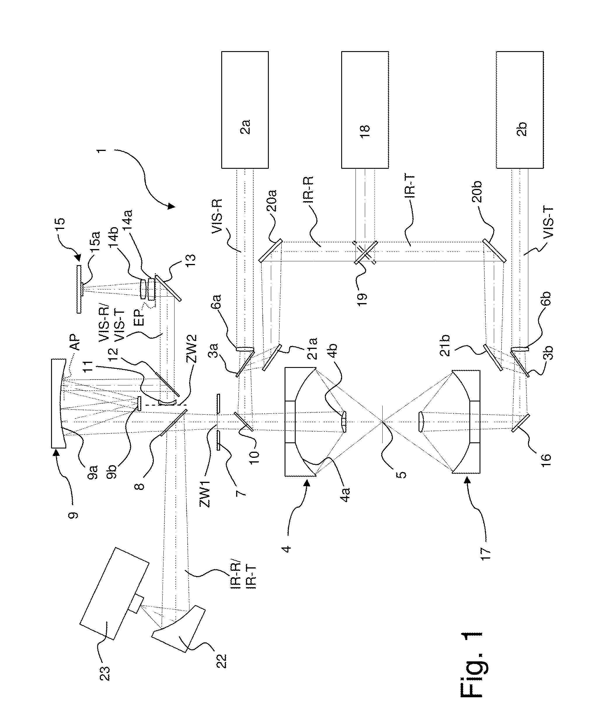
[0031]FIG. 1 shows a schematic overview of an embodiment of an inventive IR microscope 1. The IR microscope 1 can be used both in reflection operation (“front lighting”) and in transmission operation (“back lighting”).

[0032]In reflection operation in optical viewing mode, visible light (see beam path VIS-R) is directed from a source 2a of visible light (for example, an incandescent bulb) via a lens 6a, a beam splitter 3a, a beam splitter 10, and a Cassegrain objective 4 onto a sample position 5, at which a sample to be examined is disposed. The Cassegrain objective 4 comprises two reflective surfaces 4a, 4b; in this case, the convex surface 4b and the concave surface 4a are each spherically curved.

[0033]The visible light reflected from the sample position 5 is imaged onto a first intermediate focus ZF1 via the Cassegrain objective 4 through the beam splitter 10, wherein the Cassegrain objective 4 introduces a field curvature aberration. In the plane of the first intermediate focus Z...


PUM


Abstract

An IR microscope (1) is constituted such that, in an optical viewing mode in a beam path of visible light (VIS-R, VIS-T), a first intermediate focus (ZW1) is imaged onto a flat detector surface (15a) of a camera. The IR microscope (1) is constituted such that, in the beam path of the visible light (VIS-R, VIS-T), the first intermediate focus (ZW1) is imaged onto a second intermediate focus (ZW2), and, in the second intermediate focus (ZW2), a Mangin mirror (11) is disposed that corrects a field curvature of the Cassegrain objective (4). The invention provides an IR microscope in which the field curvature generated by the Cassegrain objective is corrected in a simple manner in the optical viewing mode when detection is performed using a flat detector and without restricting the spectral range of the IR microscope.

Description

[0001]This application claims Paris convention priority of DE 10 2012 200 851.9 filed Jan. 20, 2012, the entire disclosure of which is hereby incorporated by reference.BACKGROUND OF THE INVENTION[0002]The invention relates to an infrared (=IR) microscope,with a beam path for visible light and a beam path for IR light,wherein the beam paths are coextensive in the region of a sample position, of a Cassegrain objective, and of a first intermediate focus,wherein the Cassegrain objective images the sample position onto the first intermediate focus,and wherein the IR microscope is constituted in such a way as to direct IR light from the first intermediate focus to an IR detector at least in an IR viewing mode, and to image the first intermediate focus onto a flat viewing surface, in particular a flat detector surface of a camera, in the beam path of the visible light at least in an optical viewing mode.[0003]Such an IR microscope is known from the company publication “HYPERION Series” of ...

Claims


Application Information

Patent Timeline
IPC IPC(8): G02B21/36G02B21/00
CPCG02B21/04G02B21/0096G02B21/361G02B21/0004G02B17/061G02B17/0816G02B13/14
Inventor JUETTE, MICHAELKEENS, AXEL
Owner BRUKER OPTICS GMBH & CO KG
Why Eureka
Try Eureka