Laser targeting viewing device and method
a laser targeting and viewing device technology, applied in the direction of movable markers, distance measurement, instruments, etc., can solve the problem that the ideal way to determine is not the guide pointing to the animal
- Summary
- Abstract
- Description
- Claims
- Application Information
AI Technical Summary
Benefits of technology
Problems solved by technology
Method used
Image
Examples
second embodiment
[0015]a viewing device in accordance with the present disclosure is a pair of targeting binoculars 200 as is shown in a perspective view in FIG. 3 and in a side view in FIG. 4. A laser pointer / targeting assembly 202 is fastened to one of the hinges of a conventional pair of binoculars 201. The exemplary pair of binoculars illustrated is a pair of roof prism system binoculars.
[0016]The Laser targeting assembly 202 on this exemplary set of binoculars 201 has an elongated, rectangular cylinder body 203 that houses the electronics for the laser, and has an on / off switch 204 extending axially rearward at its rear end. A battery power supply 210 is connected to the electronics via a wire cord 212. This battery supply 210 may be fastened to one of the binocular barrels by any suitable means, or, if the cord 212 is long enough, the supply 210 can be carried in one of the viewing device user's pockets. Alternatively, the battery power supply may be miniaturized and housed within the body 203...
first embodiment
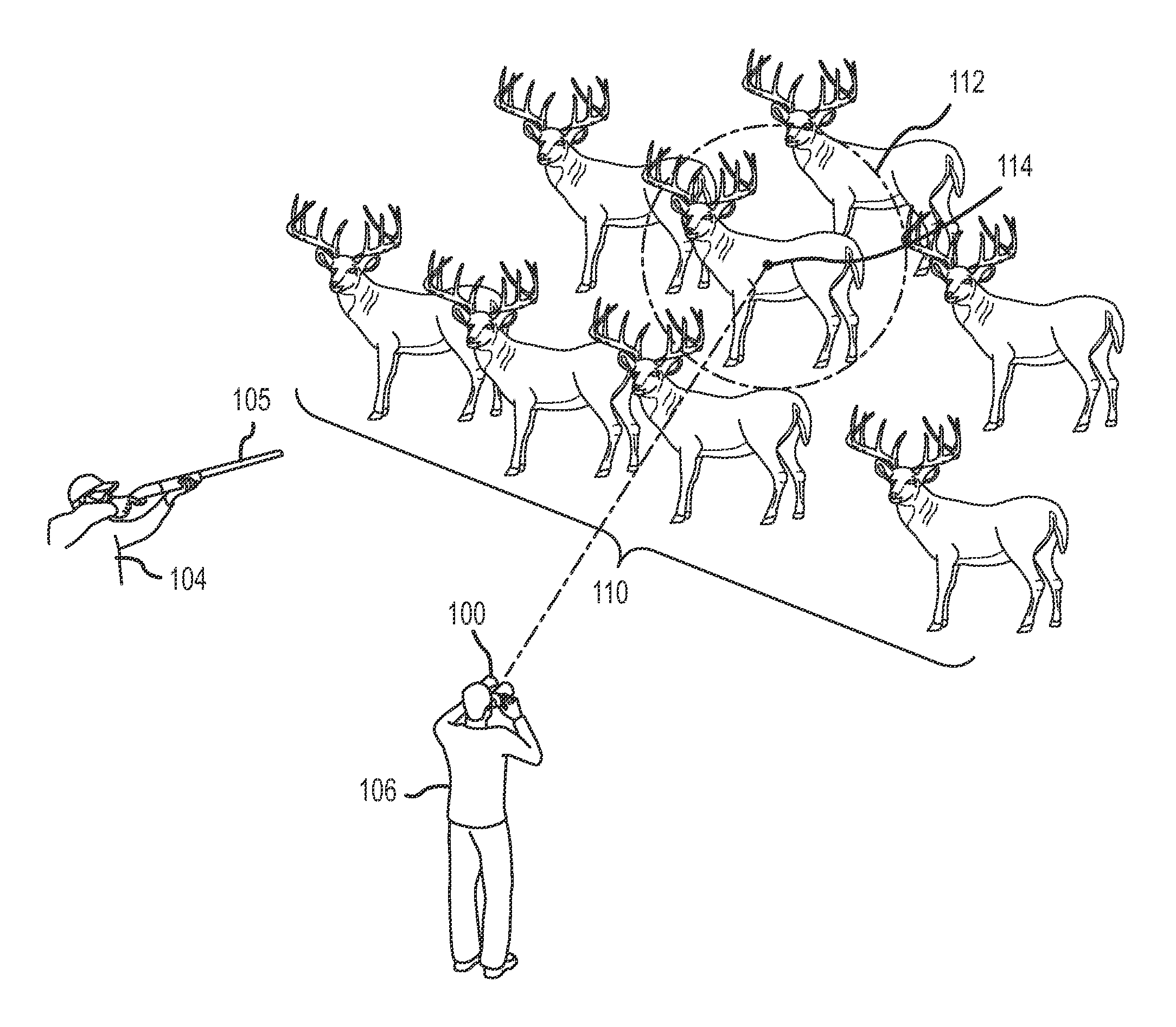
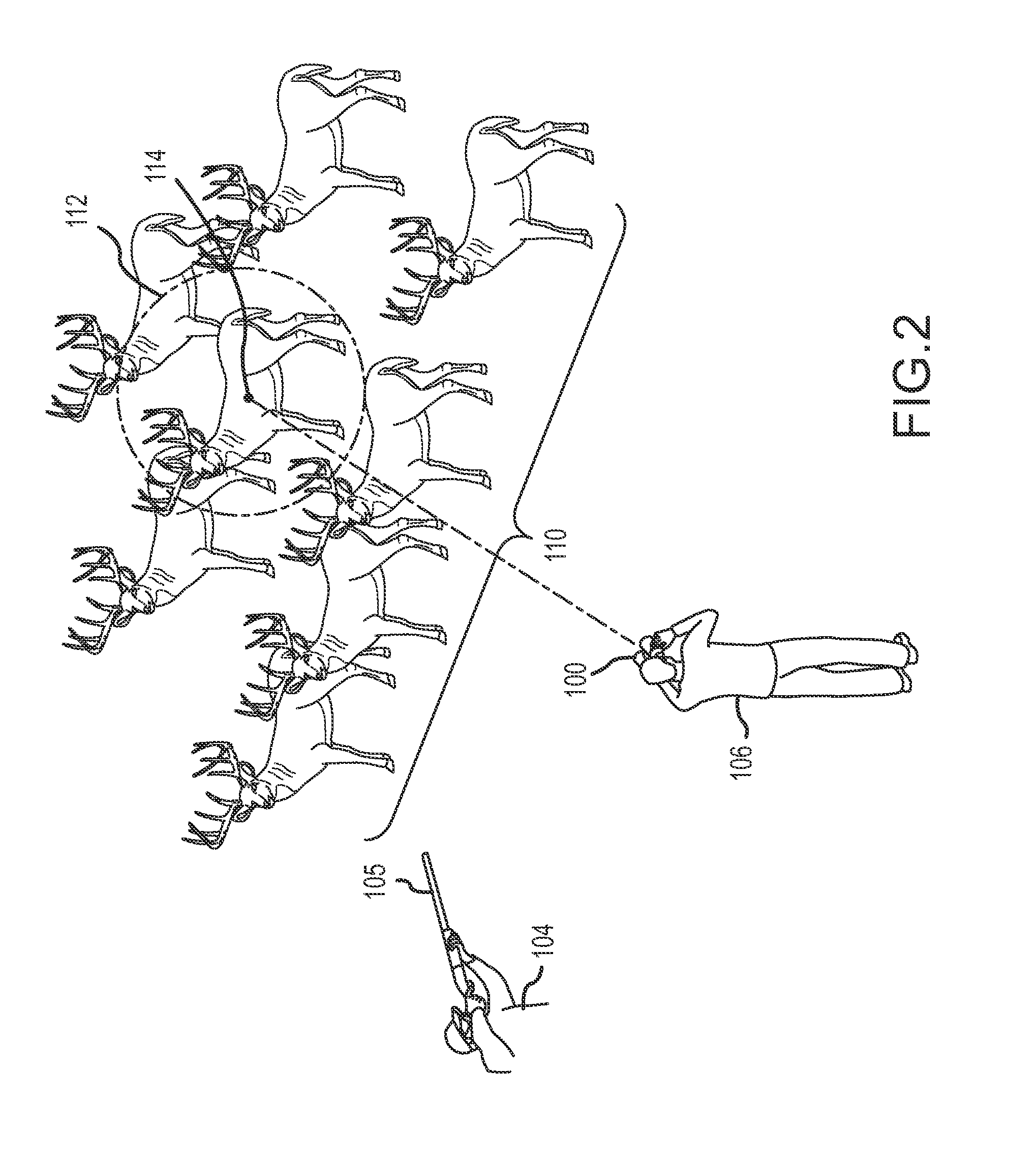
[0017]The front end of the body 203 is fastened to a front laser portion 205 that carries the optical elements of the laser. The front portion 205 has a flange 206 for fastening the assembly 202 to the hinge screw 208 of the binoculars 201. The laser assembly 202 is adjusted on the hinge screw 208 such that the laser points coincident with the center of the view field of the binoculars 201 so that the user can easily point the laser spot 114 on the target animal as shown in FIG. 2 and described above with reference to the
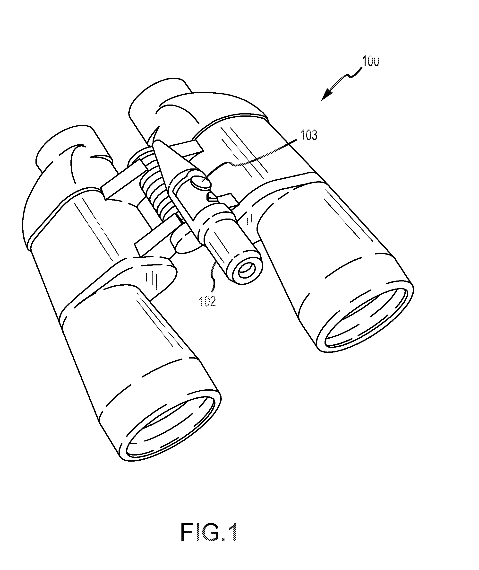
[0018]Many variations of the target viewing device exemplified by the targeting binoculars 100 and 200 can be made. The pointer 102 may be integrated into the binocular housing itself. The pointer 102 may alternatively be attached to or integrated into a monocular or conventional spotting scope, or any other viewing device, and may alternatively attached to a camera. The laser assembly 202, for example, may be furnished with a Velcro type hook and loop type fastener...
embodiment 300
[0019]An alternative viewing device 300 with a laser targeting assembly 302 mounted on the barrel of a spotting scope 301 is shown in FIG. 5. In this embodiment, a removable configuration, the flange 206 that is shown in FIGS. 3 and 4 is modified. The laser targeting assembly 302 again has an elongated body 303 attached to or integral with a laser portion 305. The body 303 carries a switch 304 for energizing the laser targeting light beam that is projected by the assembly 302. The laser portion 305 of the body 302 includes a flange 306 that has an axially extending leg that extends parallel to the body 302. The flange leg 308 is spaced from the body 302 just enough to receive a strap 310 of hook and loop fastener material that is snugly wrapped around the barrel of the spotting scope 301 rather than receiving a mounting screw 208 as shown in FIGS. 3 and 4 to fasten the assembly 202 in place. In this embodiment 300, the battery power supply is preferably miniaturized and housed withi...
PUM
 Abstract
Description
Claims
Application Information
 - R&D
- Intellectual Property
- Life Sciences
- Materials
- Tech Scout
- Unparalleled Data Quality
- Higher Quality Content
- 60% Fewer Hallucinations
Browse by: Latest US Patents, China's latest patents, Technical Efficacy Thesaurus, Application Domain, Technology Topic, Popular Technical Reports.
© 2025 PatSnap. All rights reserved.Legal|Privacy policy|Modern Slavery Act Transparency Statement|Sitemap|About US| Contact US: help@patsnap.com


