

Clip for use in a disc brake assembly and disc brake assembly including such a clip
a technology for disc brakes and disc brake assemblies, which is applied in the direction of brake systems, mechanical equipment, transportation and packaging, etc., can solve the problems of brake pads seizing, brake dust, corrosion, etc., and unfavorable rattle or other noises,
- Summary
- Abstract
- Description
- Claims
- Application Information
AI Technical Summary
Benefits of technology
Problems solved by technology
Method used
Image

Examples
first embodiment
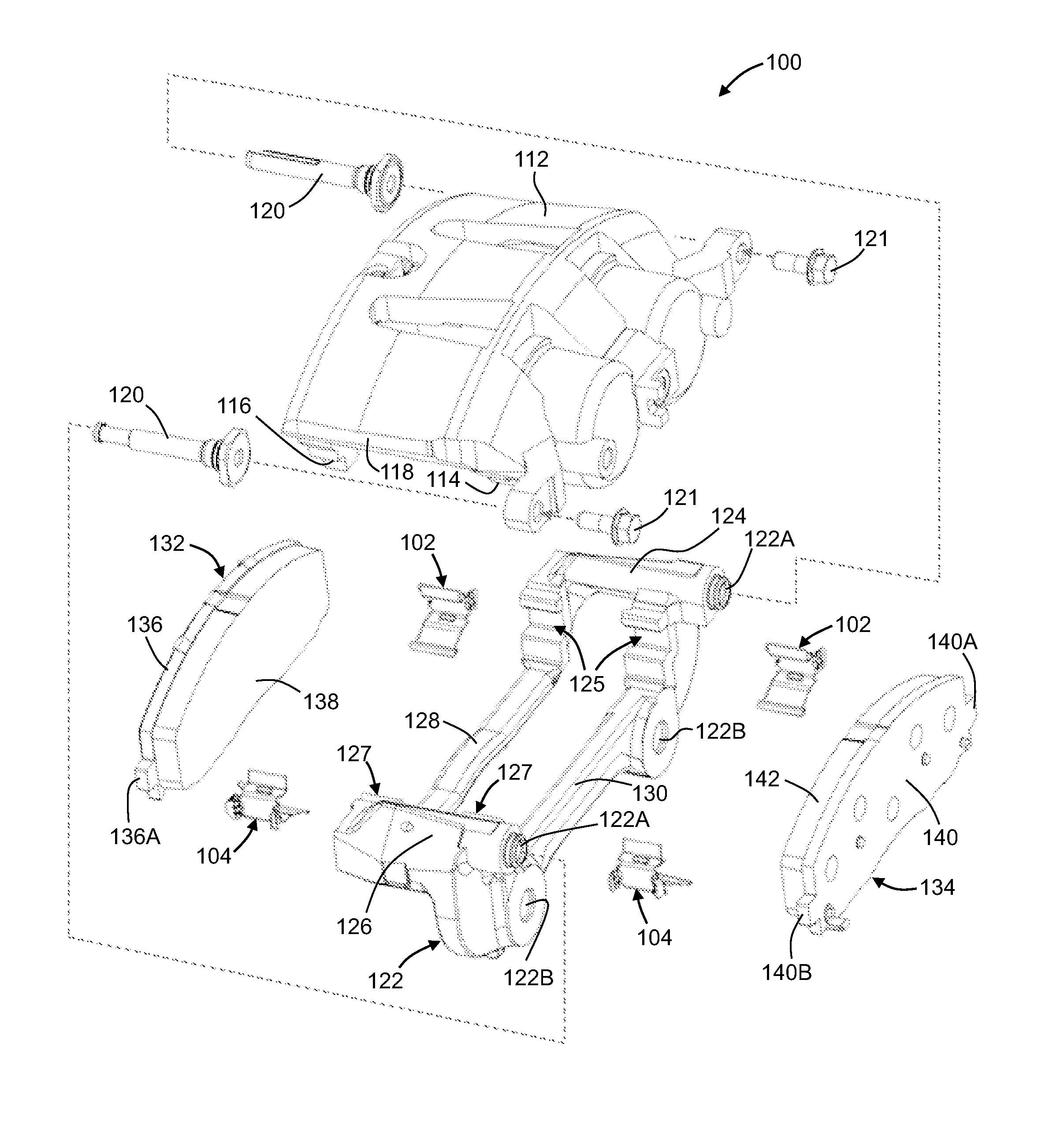
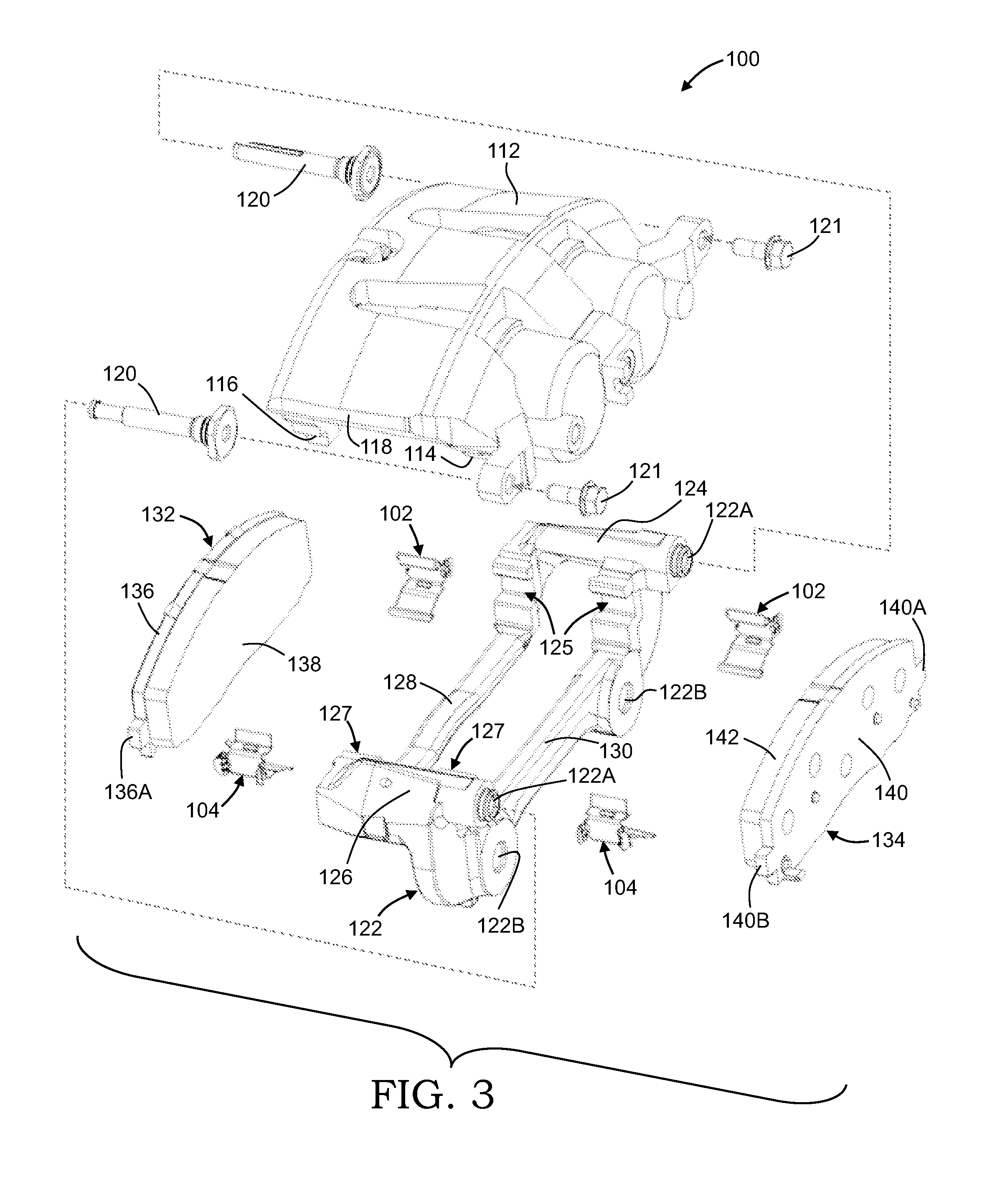
[0053]Referring now to FIG. 3, there is illustrated a perspective view of selected components of a disc brake assembly, indicated generally at 100, including a first pair of brake clips 102 and a second pair of brake clips 104 shown in an uninstalled position thereon, in accordance with the present invention. The disc brake assembly 100 that is illustrated in FIG. 3 is a well known “Collete” sliding type of disc brake assembly. The general structure and operation of the disc brake assembly 100 is conventional in the art. Thus, only those portions of the disc brake assembly 100 which are necessary for a full understanding of this invention will be explained and illustrated in detail. Also, although this invention will be described and illustrated in connection with the particular disc brake assembly 100 disclosed herein, it will be appreciated that this invention may be used in connection with other types of disc brake assemblies. For example, the invention may be used in conjunction...
third embodiment
[0072]Referring now to FIG. 7, there is illustrated a brake clip, indicated generally at 302, in accordance with the present invention. The brake clip 302 may include any structural features as described and illustrated above in the previous embodiments, although such is not required. Similar features have been numbered with common reference numerals but have been increased to 300 (e.g. 302, 322, 332, etc.). It should be appreciated that similar features are structured similarly, operate similarly, and / or have the same function unless otherwise indicated by the drawings or this specification.
[0073]For example, the illustrated brake clip 302 includes a base leg 360, upper and lower legs 361 and 362, a pair of retaining members 363A and 363B, a plurality of retention tabs 364A and 364B, a first support leg 366, and an extension leg 367. However, in this embodiment the upper leg 361 includes a pair of generally square shaped retention tabs 364A that extends downwardly therefrom. As sho...
fourth embodiment
[0074]Referring now to FIG. 8, there is illustrated a brake clip, indicated generally at 402, in accordance with the present invention. The brake clip 402 may include any structural features as described and illustrated above in the previous embodiments, although such is not required. Similar features have been numbered with common reference numerals but have been increased to 400 (e.g. 402, 422, 432, etc.). It should be appreciated that similar features are structured similarly, operate similarly, and / or have the same function unless otherwise indicated by the drawings or this specification.
[0075]For example, the illustrated brake clip 402 includes a base leg 460, upper and lower legs 461 and 462, a pair of retaining members 463A and 463B, a plurality of retention tabs 464A and 464B, a first support leg 466, and an extension leg 467. However, in this embodiment the upper leg 461 includes a pair of generally triangular shaped retention tabs 464A that extends upwardly therefrom. As s...
PUM
 Abstract
Description
Claims
Application Information