Charged particle accelerator and particle beam therapy system

a particle accelerator and charge technology, applied in the field of particle beam therapy system, can solve the problems of massive amount of hard disk or memory for storing data, large amount of pattern data, and large overall charge of particle accelerator, and achieve the effect of reducing the time for pattern data communication with the accelerator

Active Publication Date: 2013-08-01
MITSUBISHI ELECTRIC CORP
View PDF7 Cites 13 Cited by
  • Summary
  • Abstract
  • Description
  • Claims
  • Application Information

AI Technical Summary

Benefits of technology

[0011]In a charged particle accelerator according to the present invention, an acceleration cavity and a deflection electromagnet are controlled by use of an acceleration cavity clock and an electromagnet clock that is synchronized with the acceleration cavity clock and has a frequency low

Problems solved by technology

In the case where the deflection electromagnet and the high-frequency acceleration cavity are operated by use only a T-clock, the amount of pattern data to be dealt with by the overall charged particle accelerato

Method used


Image

  • Charged particle accelerator and particle beam therapy system
  • Charged particle accelerator and particle beam therapy system
  • Charged particle accelerator and particle beam therapy system

Examples


embodiment 1

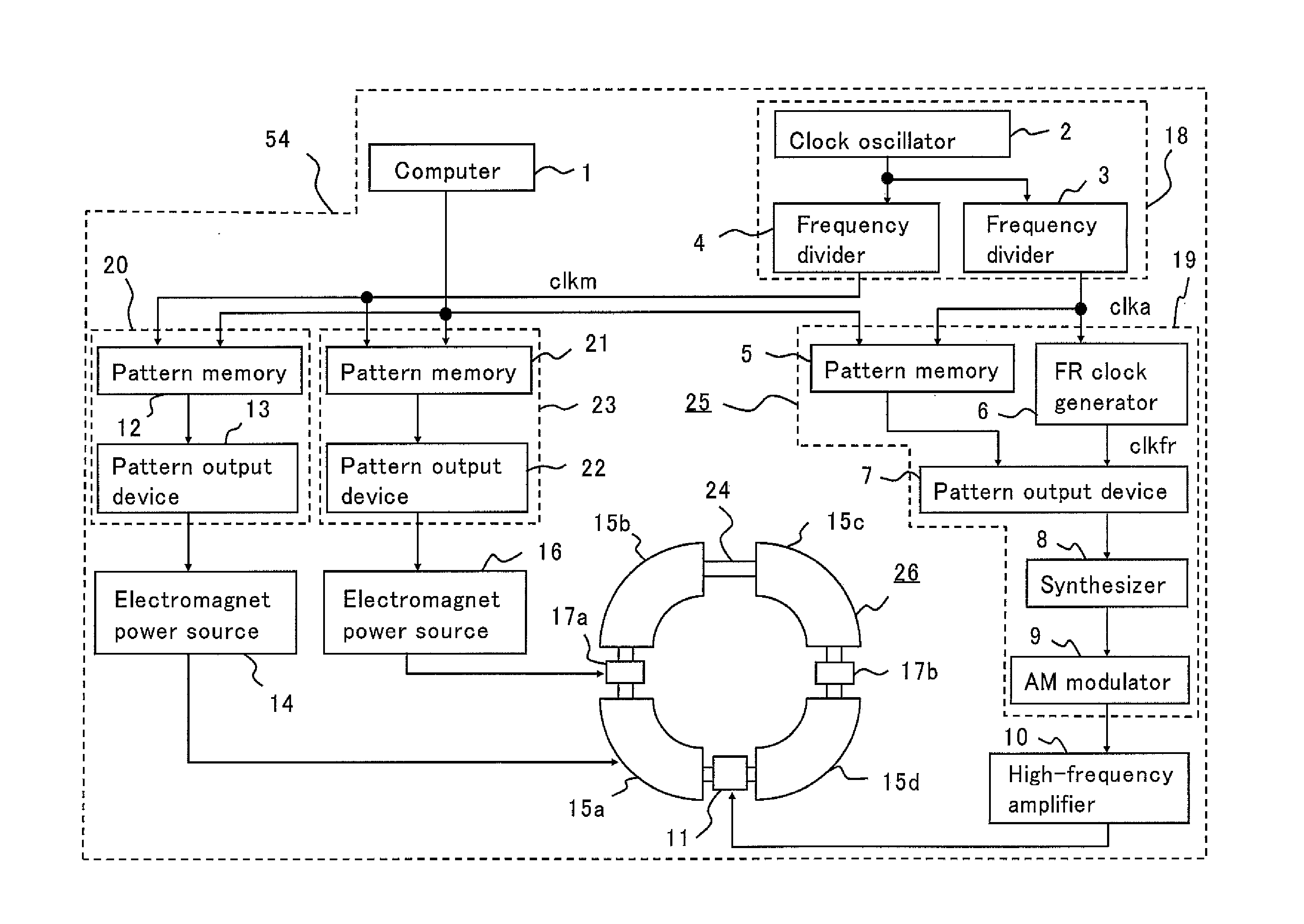
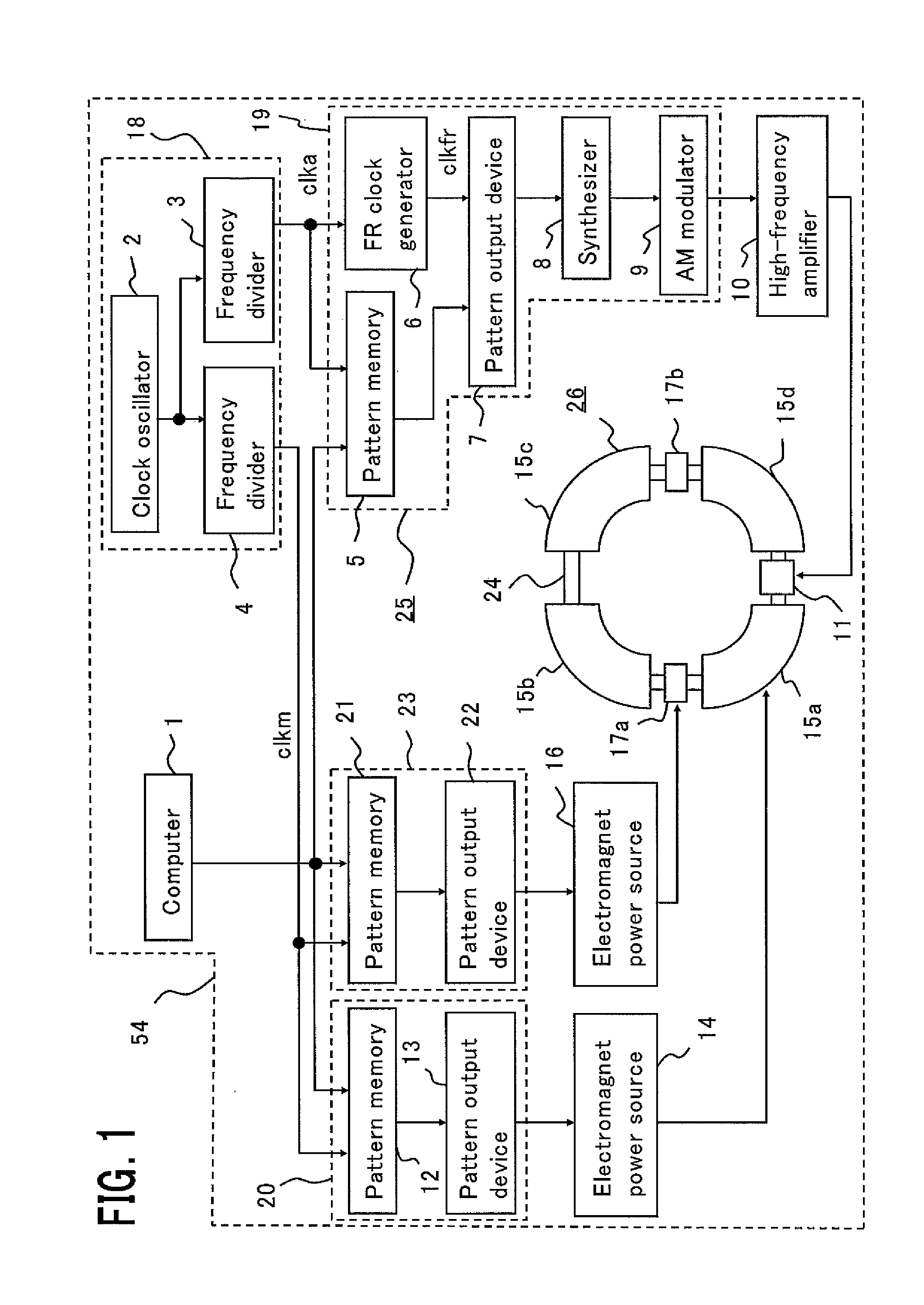
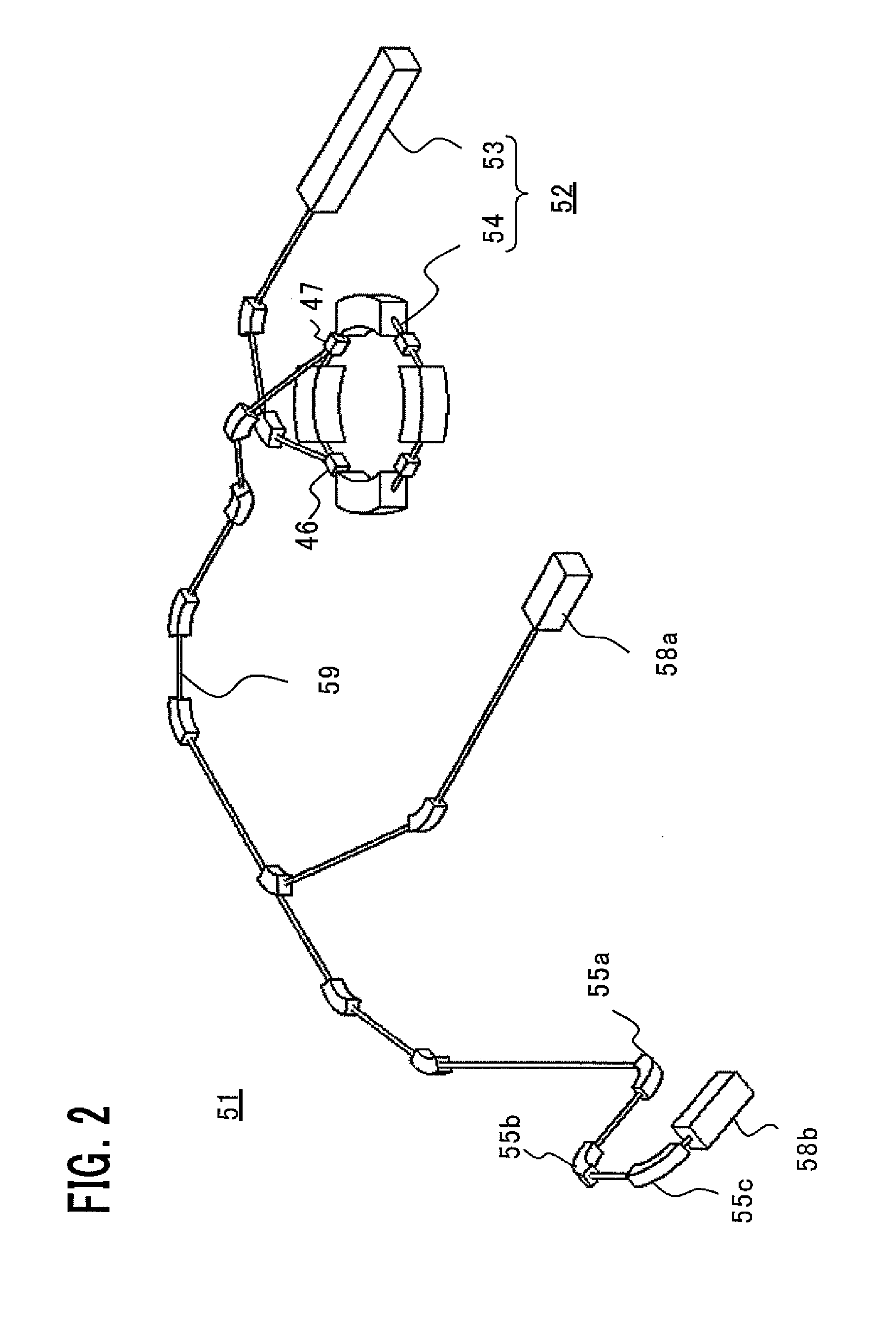
[0020]FIG. 1 is a diagram illustrating the configuration of a charged particle accelerator according to Embodiment 1 of the present invention. FIG. 2 is a schematic configuration diagram illustrating a particle beam therapy system according to Embodiment 1 of the present invention; FIG. 3 is a diagram illustrating the configuration of a particle beam irradiation apparatus according to Embodiment 1 of the present invention. In FIG. 2, a particle beam therapy system 51 includes a beam generation apparatus 52, a beam transport system 59, and particle beam irradiation apparatuses 58a and 58b. The beam generation apparatus 52 includes an ion source (unillustrated), a prestage accelerator 53, and a charged particle accelerator 54. The particle beam irradiation apparatus 58b is provided in a rotating gantry (unillustrated). The particle beam irradiation apparatus 58a is provided in a treatment room where no rotating gantry is installed. The function of the beam transport system 59 is to ac...

embodiment 2

[0060]FIG. 7 is a diagram illustrating the configuration of a charged particle accelerator according to Embodiment 2 of the present invention. A charged particle accelerator 54 according to Embodiment 2 is different from the charged particle accelerator 54 according to Embodiment 1 in that the FR clock generator 6 is eliminated and the frequency of the acceleration cavity clock clka and the amount of the frequency data of the acceleration cavity pattern stored in the pattern memory 5 are different. In this Description, there will be explained an example in which the outputting frequency of the frequency data explained in Embodiment 1 is the same.

[0061]In Embodiment 1, the pattern output device 7 outputs the frequency data of the acceleration cavity pattern to the synthesizer 8, by use of the FR clock clkfr of 1.2 MHz. Thus, in Embodiment 2, the frequency divider 3 generates the acceleration cavity clock clka of 1.2 MHz. Specifically, in Embodiment 2, a reference clock of 12 MHz is g...


PUM


Abstract

The objective is to obtain a charged particle accelerator where the amount of pattern data for operating an acceleration cavity and electromagnets based on time clocks is reduced and the pattern data communication time is shortened. An accelerator control apparatus provided in a charged particle accelerator of the present invention is characterized by including a clock generation unit that generates an acceleration cavity clock and an electromagnet clock that is synchronized with the acceleration cavity clock and has a frequency lower than that of the acceleration cavity clock; a high-frequency control unit that controls an acceleration cavity, based on an acceleration cavity pattern stored in a first pattern memory and the acceleration cavity clock; and a deflection electromagnet control unit that controls a deflection electromagnet, based on a deflection electromagnet pattern stored in a second pattern memory and the electromagnet clock.

Description

TECHNICAL FIELD[0001]The present invention relates to a particle beam therapy system that is utilized in the medical field.BACKGROUND ART[0002]In general, a particle beam therapy system is provided with a beam generation apparatus that generates a charged particle beam; an accelerator that is connected with the beam generation apparatus and accelerates a generated charged particle beam; a beam transport system that transports a charged particle beam that is accelerated by the accelerator so as to gain predetermined energy and then emitted; and a particle beam irradiation apparatus, disposed at the downstream side of the beam transport system, for irradiating a charged particle beam onto an irradiation subject.[0003]As an accelerator for accelerating a charged particle beam, for example, a synchrotron is utilized. A high-frequency wave is applied to a high-frequency acceleration cavity (acceleration cavity) provided in a synchrotron; pattern operation is implemented with a deflection...

Claims


Application Information

Patent Timeline
IPC IPC(8): H05H13/04A61N5/10
CPCH05H2007/046A61N2005/1087H05H13/04H05H2277/11
Inventor IKEDA, MASAHIROKIJIMA, YUKOOKADA, SHUNSUKE
Owner MITSUBISHI ELECTRIC CORP
Why Eureka
Try Eureka