Power-shiftable transmission

a transmission and power technology, applied in mechanical equipment, transportation and packaging, gearing, etc., can solve the problems of drag losses in the known transmission, and high cost and space occupation, so as to minimize the space occupied by the transmission and drag losses

Active Publication Date: 2013-08-01
ZF FRIEDRICHSHAFEN AG
View PDF3 Cites 11 Cited by
  • Summary
  • Abstract
  • Description
  • Claims
  • Application Information

AI Technical Summary

Benefits of technology

[0005]The purpose of the present invention is to propose a transmission of the type described at the start, in which drag losses and also the space occupied by the transmission are minimized.
[0007]Thus a transmission, in particular a planetary transmission is proposed, which comprises as few power-shiftable, frictional shifting elements as possible, regardless of whether besides the at least one planetary gearset one or more spur gear stages are also provided. Since the power density of interlocking shifting elements is much greater than that of frictional shifting elements, in contrast to frictional shifting elements when interlocking shifting elements are in the open condition they are virtually free from drag losses. In this way not only are the drag losses that occur with frictional shifting elements reduced, but also the production costs and structural space occupation can be reduced substantially since as many interlocking, unsynchronized shifting elements as possible, such as shifting claws or the like, are used.
[0009]In an advantageous embodiment of the invention it can also be provided that in addition, at least one interlocking shifting element is associated with a gear step as a shifting element to be shifted “off”. In this way the number of frictional shifting elements required can be reduced still more.
[0011]When selecting a suitable supporting gear it should be borne in mind that the change from the initial or current gear to the supporting gear concerned should entail changing only one shifting element or opening one shifting element and closing or engaging one other power-shifting element or supporting shifting element. Moreover, to change from the supporting gear to the desired target gear only the supporting shifting element should be opened and the interlocking or claw shifting element, which is the new shifting element to be shifted to “on”, should be actuated. Advantageously, all the other shifting elements that are closed in the gears involved remain closed during the shifting process, or are at most brought to a slipping condition for a short time.
[0012]With the idea on which the invention is based, that of using interlocking shifting elements also for shifting elements being shifted to “on” and using supporting gears in the shifting processes concerned, in order to achieve the necessary synchronization an automatic transmission can advantageously be produced which, besides the claw shifting elements provided as its interlocking shifting elements, is designed with only two frictional shifting elements. In this way, with the same number of gears drag torques can be very greatly reduced without adverse effect on the power-shifting ability. Preferably for example, the frictional shifting elements used can also be ones with low drag torque, which are subjected to less thermal stress.
[0013]For example, if the transmission according to the invention has only two frictional shifting elements, these can be engaged together in the highest gear and, in lower gears, individually with at least one interlocking or claw shifting element. Gear steps below the gears with engaged frictional shifting elements can be engaged by means of supporting shifting elements without loss of traction force during the shift. The smaller the gear interval between the current gear and the supporting gear, the less the traction force is limited during the shift. Expediently, a selected supporting gear should only be one gear step, or at most three gear steps higher than the target gear to be engaged.

Problems solved by technology

However, such automatic transmissions have the disadvantage that all their shifting elements are in the form of frictional disk clutches or disk brakes, which take up a lot of space and are cost-intensive.
Owing to the numerous frictional shifting elements used, drag losses in the known transmission and also its costs and space occupation are high.

Method used


Image

  • Power-shiftable transmission
  • Power-shiftable transmission
  • Power-shiftable transmission

Examples


first embodiment

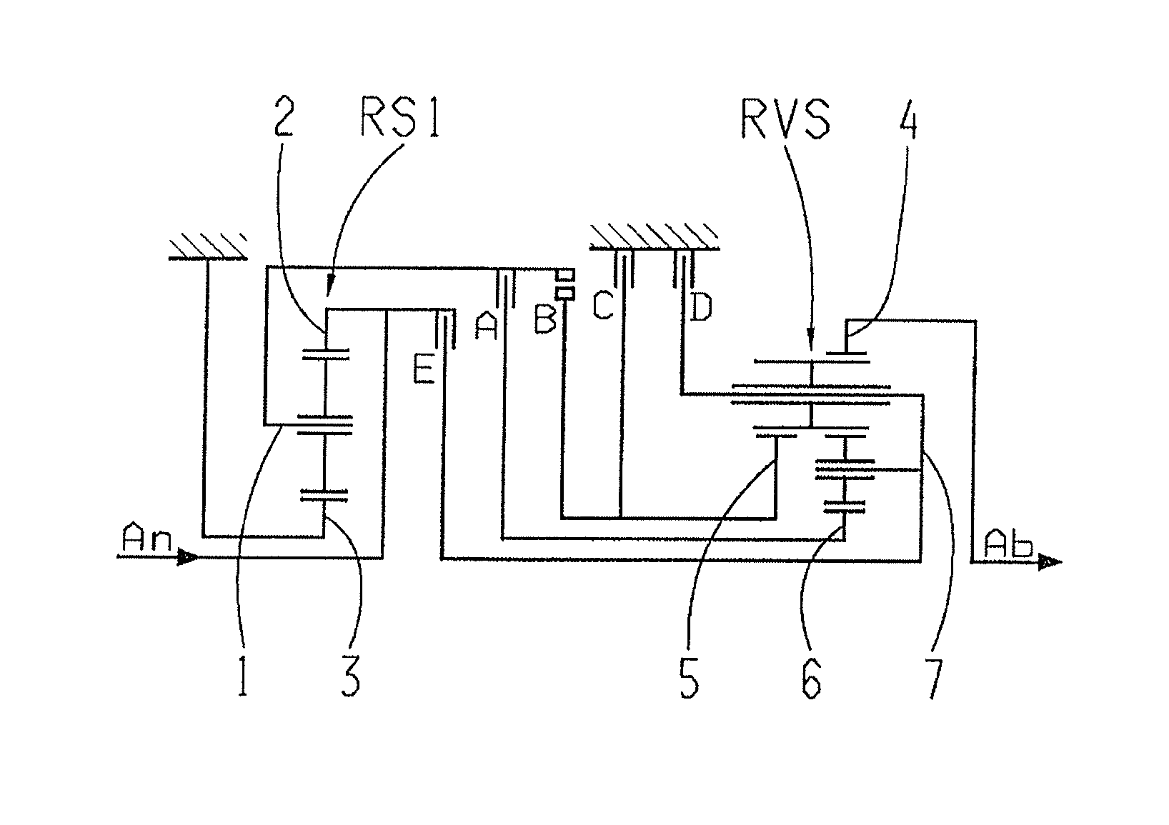
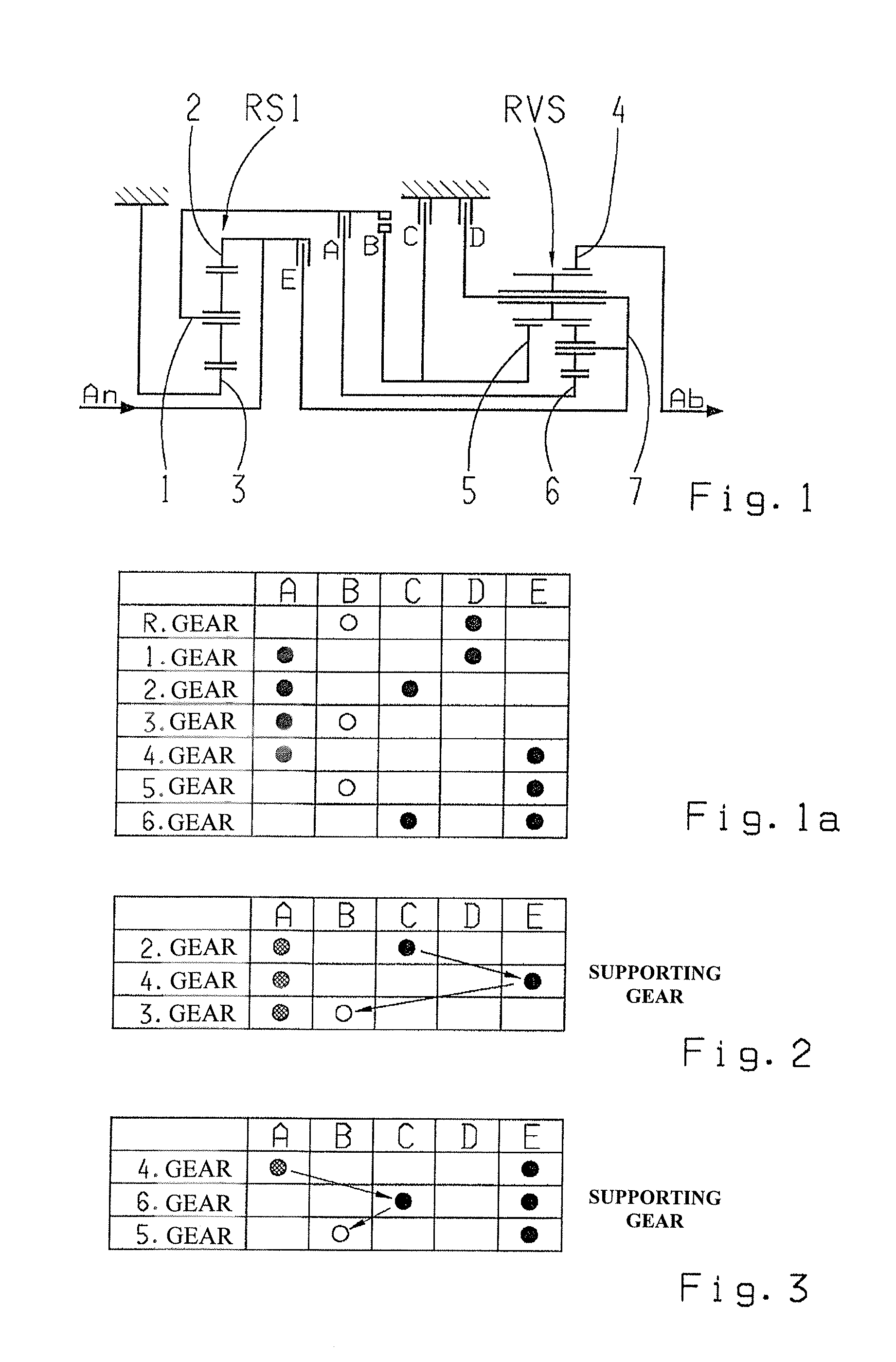
[0034]FIG. 1 shows a first embodiment variant of the transmission according to the invention in the form of a planetary transmission with a first planetary gearset RS1 and a second gearset in the form of a dual planetary gearset of Ravigneaux design RVS, and with five shifting elements A, B, C, D and E.

[0035]In the gear arrangement according to FIG. 1, a planetary carrier 1 of the first planetary gearset RS1 is connected to the first shifting element A which is a friction clutch and to the second shifting element B which is a claw clutch, and a ring gear 2 of the first planetary gearset RS1 is connected to a drive input shaft An and to the fifth shifting element E, which is a friction clutch. A sun gear 3 of the first planetary gearset RS1 is connected to the housing. In addition, a ring gear 4 of the Ravigneaux gearset RVS is connected to a drive output shaft Ab and a first sun gear 5 of the Ravigneaux gearset RVS is connected to the second shifting element B, which is a claw clutc...

third embodiment

[0046]FIG. 7 shows a third embodiment variant of the invention, which is a power-shiftable, six-gear planetary transmission with three planetary gearsets RS1, RS2, RS3 and five shifting elements A, B, C, D and E. In this gear arrangement a sun gear 3 of the first planetary gearset RS1 is connected to the drive input shaft An, to the first shifting element A which is a friction clutch, and to the second shifting element B which is also a friction clutch. A ring gear 2 of the first planetary gearset RS1 is connected to the third shifting element C which is a claw brake, and a planetary carrier 1 of the first planetary gearset RS1 is connected to the fourth shifting element D which is a friction brake and to a ring gear 8 of the second planetary gearset RS2. Furthermore, a planetary carrier 9 of the second planetary gearset RS2 is connected, on the one hand, to the second shifting element B which is a friction clutch and, on the other hand, to a fifth shifting element E which is a fric...

fourth embodiment

[0049]FIG. 8 shows a fourth embodiment variant of the invention, which is a power-shiftable, eight-gear planetary transmission with a plus planetary gearset PRS and a Ravigneaux gearset RVS and with six shifting elements A, B, C, D, E and F of which, as interlocking shifting elements, the second shifting element B is in the form of a claw clutch and the sixth shifting element F is in the form of a claw brake.

[0050]In this gear arrangement a sun gear 13 of the plus planetary gearset PRS is fixed onto the housing and a planetary carrier 14 of the plus planetary gearset PRS is connected, on the one hand, to the sixth shifting element F which is a claw clutch and, on the other hand, to the drive input shaft An and to the fifth shifting element E which is a friction clutch. Furthermore a ring gear 15 of the plus planetary gearset PRS is connected to the first shifting element A which is a friction clutch and to the second shifting element B which is a claw clutch. A ring gear 4 of the Ra...


PUM


Abstract

A power-shiftable transmission, in particular an automatic transmission for a vehicle, which comprises a plurality of frictional shifting elements and at least one interlocking shifting element (A, B, C, D, E) and a plurality of gearwheels which can be engaged in a power flow by the shifting elements (A, B, C, D, E). In order to engage a gear step, at least two associated shifting elements (A, B, C, D, E) are engaged and at least one interlocking shifting element (B), as a shifting element (B) to be engaged, is associated with a gear step to be engaged with a supporting gear.

Description

[0001]This application is a National Stage completion of PCT / EP2011 / 066188 filed Sep. 19, 2011, which claims priority from German patent application serial no. 10 2010 042 656.3 filed Oct. 20, 2010.FIELD OF THE INVENTION[0002]The present invention concerns a power-shiftable transmission, in particular an automatic transmission for a vehicle.BACKGROUND OF THE INVENTION[0003]For example from the document EP 0 434 525 A1 an automatic multi-gear transmission for vehicles is known, which comprises a number of planetary gearsets which are shifted by means of frictional elements such as clutches and brakes and are usually connected to a starting element such as a hydraulic torque converter or a fluid coupling with a protective action and which is optionally provided with a bridging clutch. However, such automatic transmissions have the disadvantage that all their shifting elements are in the form of frictional disk clutches or disk brakes, which take up a lot of space and are cost-intensiv...

Claims


Application Information

Patent Timeline
Patent Type & Authority Applications(United States)
IPC IPC(8): F16H3/44
CPCF16H3/66F16H2061/0474F16H3/666F16H61/0403F16H2200/0052F16H2200/0069F16H2200/2007F16H2200/201F16H2200/2012F16H2200/2023F16H2200/2043F16H2200/2048F16H2200/2051F16H2200/2064F16H2200/2097F16H3/44F16H2200/2094F16H3/663
Inventor GUMPOLTSBERGER, GERHARDSICH, BERNHARDREISCH, MATTHIASGOETZ, MANUELMOHR, MARKDREIBHOLZ, RALFZIEMER, PETERBAUKNECHT, GERT
Owner ZF FRIEDRICHSHAFEN AG
Why Eureka
Try Eureka