Heat storage device for an engine

Inactive Publication Date: 2013-08-08
FORD GLOBAL TECH LLC
View PDF7 Cites 23 Cited by
  • Summary
  • Abstract
  • Description
  • Claims
  • Application Information

AI Technical Summary

Benefits of technology

[0003]It should be understood that the summary above is provided to introduce in simplified form a selection of concepts that are further described in the detailed description. It is not meant to identify key or essential features of the claimed subje

Problems solved by technology

The inventors herein have recognized various issues with such systems in that the available packaging space fo

Method used


Image

  • Heat storage device for an engine
  • Heat storage device for an engine
  • Heat storage device for an engine

Examples


Embodiment Construction

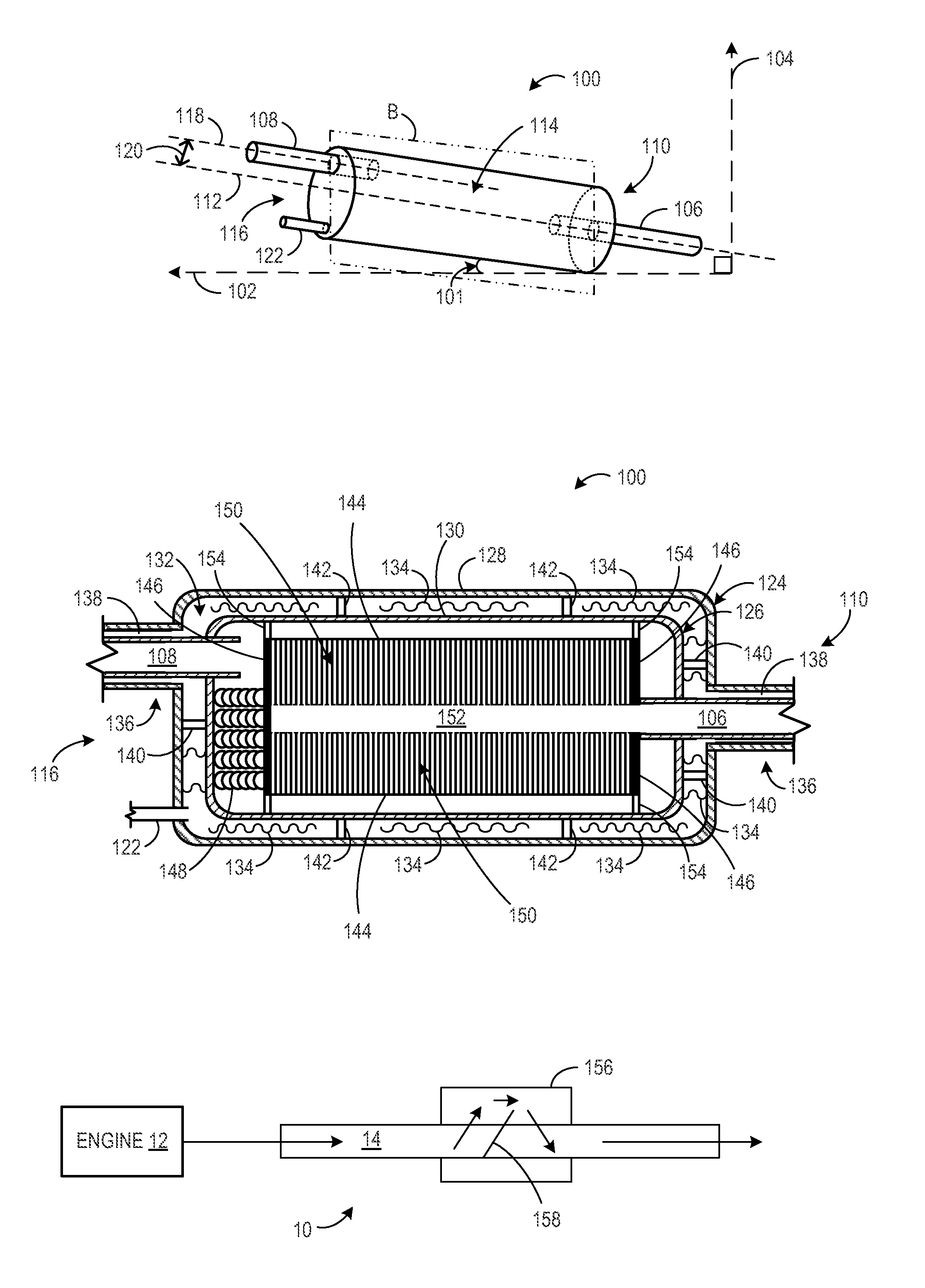
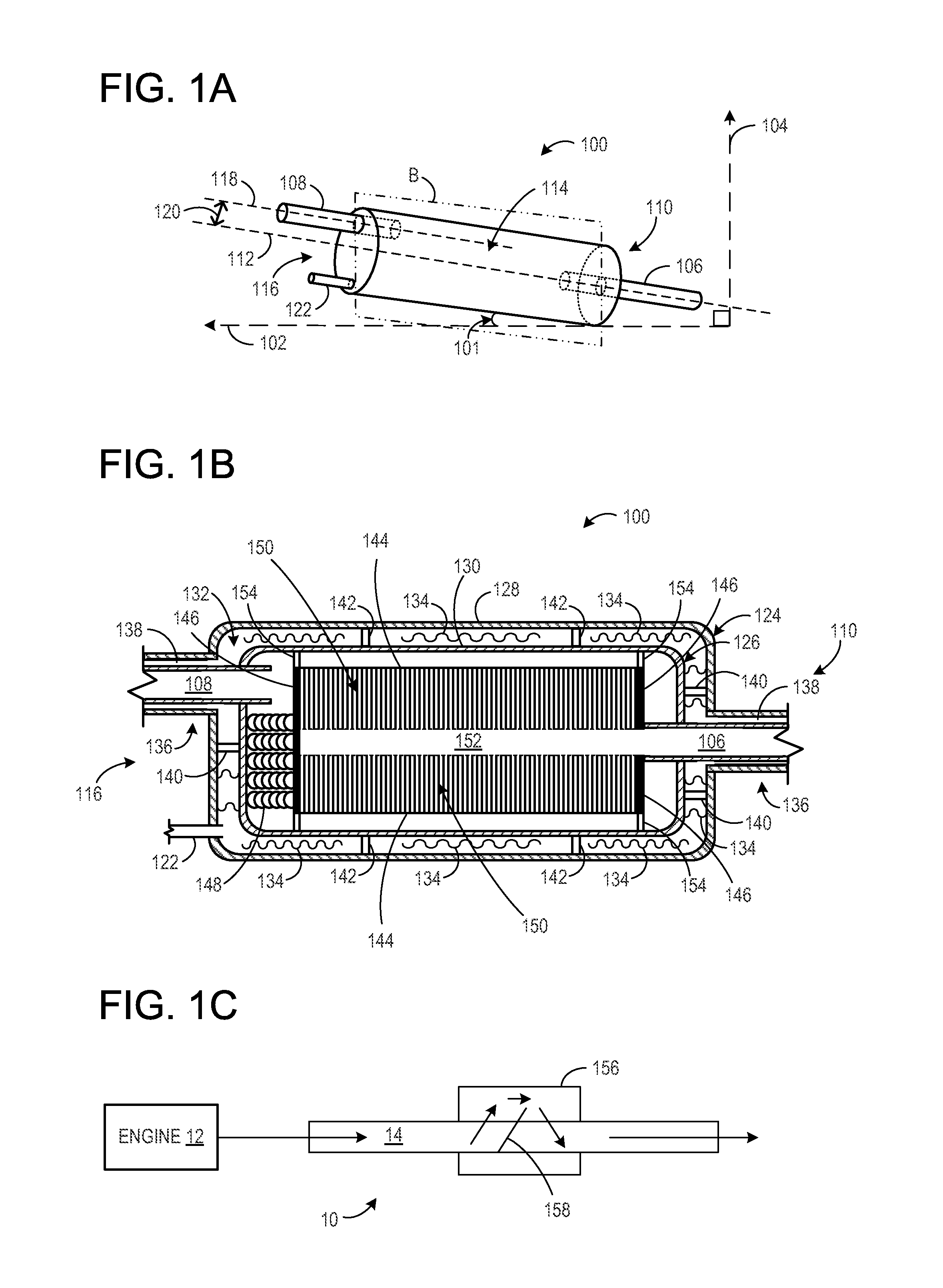
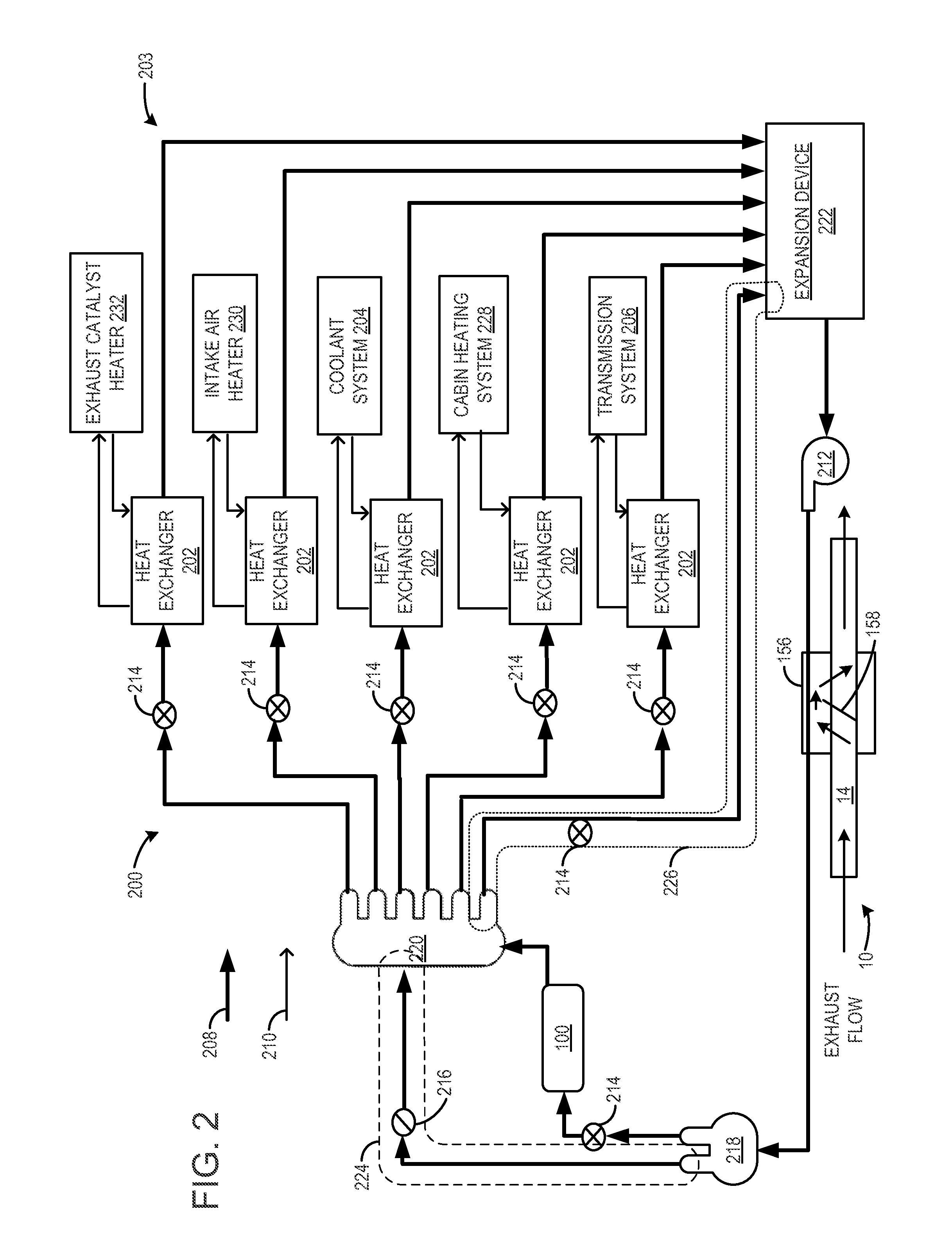
[0008]The following description relates to a heat storage device of a heat transfer system including phase changing materials, which are arranged in such a way that thermal energy from an exhaust system can be recovered. The example arrangements described herein allow thermal energy to be recovered and stored for later heating of a passenger compartment, for example.

[0009]As indicated, the heat transfer system may utilize a heat storage device to transfer heat even when the engine is not in operation. For example, the heat storage device may be in fluidic communication with an exhaust system component downstream from the catalytic converter, such as via heat exchanger. In this way, heat may transfer from the heat storage device even after the engine is no longer in operation. For example, the heat storage device may be insulated to store heat recovered from the exhaust system, which may be available for immediate use at engine start.

[0010]Additionally, the heat transfer system may i...


PUM


Abstract

A heat recovery system for an engine is disclosed herein utilizing a heat storage unit configured to store waste exhaust heat for subsequent use on engine starts in various systems. In this way, improved system operation can be obtained by re-using such waste heat.

Description

BACKGROUND AND SUMMARY[0001]Vehicles may recover exhaust heat for transfer to various other systems in an internal combustion engine.[0002]The inventors herein have recognized various issues with such systems in that the available packaging space for storing waste heat is limited, and further suitable coordination among various vehicle components is lacking. As such, one example approach to address the above issues is, claim 1.[0003]It should be understood that the summary above is provided to introduce in simplified form a selection of concepts that are further described in the detailed description. It is not meant to identify key or essential features of the claimed subject matter, the scope of which is defined uniquely by the claims that follow the detailed description. Furthermore, the claimed subject matter is not limited to implementations that solve any disadvantages noted above or in any part of this disclosure.BRIEF DESCRIPTION OF THE DRAWINGS[0004]FIGS. 1A-1B schematically...

Claims


Application Information

Patent Timeline
IPC IPC(8): F28D19/00
CPCF02G5/02F01N5/02F28D20/02Y02T10/166F01N2240/02F28D20/023Y02T10/16F28D21/0003F28F2250/06B60H1/00492B60H1/20Y02E60/145F28D20/028Y02E60/14Y02T10/12
Inventor LEVIN, MICHAELSHAIKH, FURQAN ZAFARO'NEILL, JAMES PATRICKMASCH, DONALDDEMITROFF, DANRICH HENRY
Owner FORD GLOBAL TECH LLC
Why Eureka
Try Eureka