Impulse-type underground supercharged jet drilling method and device

a supercharged jet and underground technology, applied in the direction of vibration drilling, earth drilling and mining, drilling machines and methods, etc., can solve the problems of increasing the difficulty of rock breaking, reducing the efficiency of rock breaking, and requiring very high jet pressure, so as to improve the mechanical drilling speed, improve the deep well drilling speed, and reduce the drilling cost

Active Publication Date: 2013-08-08
CHINA UNIV OF PETROLEUM (BEIJING)
View PDF9 Cites 24 Cited by
  • Summary
  • Abstract
  • Description
  • Claims
  • Application Information

AI Technical Summary

Benefits of technology

[0015]The present invention uses the drill string vibration or the WOB variation as the power source, converts the kinetic energy or potential energy of the drill string into the pressure energy of the fluid, and achieves the effect of rock breaking with the underground supercharging and the ultrahigh pressure jet, thereby improving the mechanical drilling speed and reducing the drilling cost. The basic principle is as follows: when the drill string vibrates up and down or the WOB varies, under an external force, the upper joint and the housing drive the supercharging cylinder block to move up and down relative to the supercharging piston (tool's extension or retraction), thereby intermittently supercharging the working fluid entering the supercharging cylinder block. The variation of the external force or the WOB causes the supercharging piston to move up and down relative to the supercharging cylinder block.
[0016]Part of the working fluid for drilling is discontinuously supercharged into the high pressure fluid by using the axial (longitudinal) vibration and the pressure energy of the working fluid for drilling. The high pressure working fluid is sprayed through the independent high pressure nozzle on the drill bit to form a high pressure jet, which is very helpful to improve the deep well drilling speed. The working fluid not supercharged (i.e., the normal pressure working fluid) is sprayed through the ordinary nozzle of the drill bit, so as to perform downhole drill cuttings cleaning and hydraulic auxiliary rock breaking.
[0017]The present invention has a feasible principle, a simple and reliable structure, thus can meet the requirements of underground actual usage.

Problems solved by technology

However, with the increase of the well depth, the difficulty of rock breaking increases while the efficiency of rock breaking decreases.
The conventional rock breaking methods mainly include the mechanical method and the jet hydraulic one, and the latter requires very high jet pressure.
But practices have shown that this method is unfeasible due to low efficiency, high cost and insecurity.
Although various underground superchargers emerges in china and other countries, they all have certain defects, such as complex structure, low reliability, low efficiency, or the supercharging is not enough.
However, the defects of the device include challenges in direction control and short seal life.
The Chinese patent No. 200520103214.8 discloses a “fluid supercharger”, which supercharges by using an underground plunger, while the seal life is always not well prolonged and the supercharging effect is poor.
The Chinese patent No. 200820019505.2 discloses “underground booster pump using positive displacement motor with double helical grooves”, which uses a positive displacement motor to drive a plunger to change directions through the double helical grooves, but the fluid passage is too small due to the large volume of the helical grooves, thus the erosion is serious.
The Chinese patent No. 201020125587.2 discloses an “underground drill string damping and supercharging device”, which uses a spring controlled valve to implement reciprocating supercharging, but the spring does cannot guarantee working stably and reliably enough underground, and the supercharged value will be decreased.

Method used


Image

  • Impulse-type underground supercharged jet drilling method and device
  • Impulse-type underground supercharged jet drilling method and device
  • Impulse-type underground supercharged jet drilling method and device

Examples


Embodiment Construction

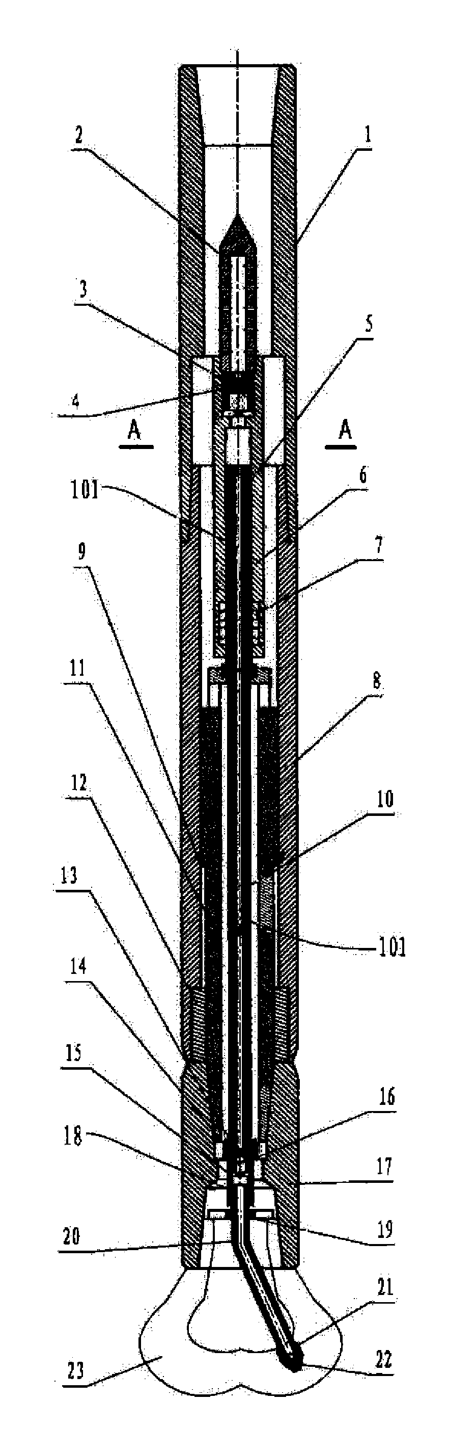
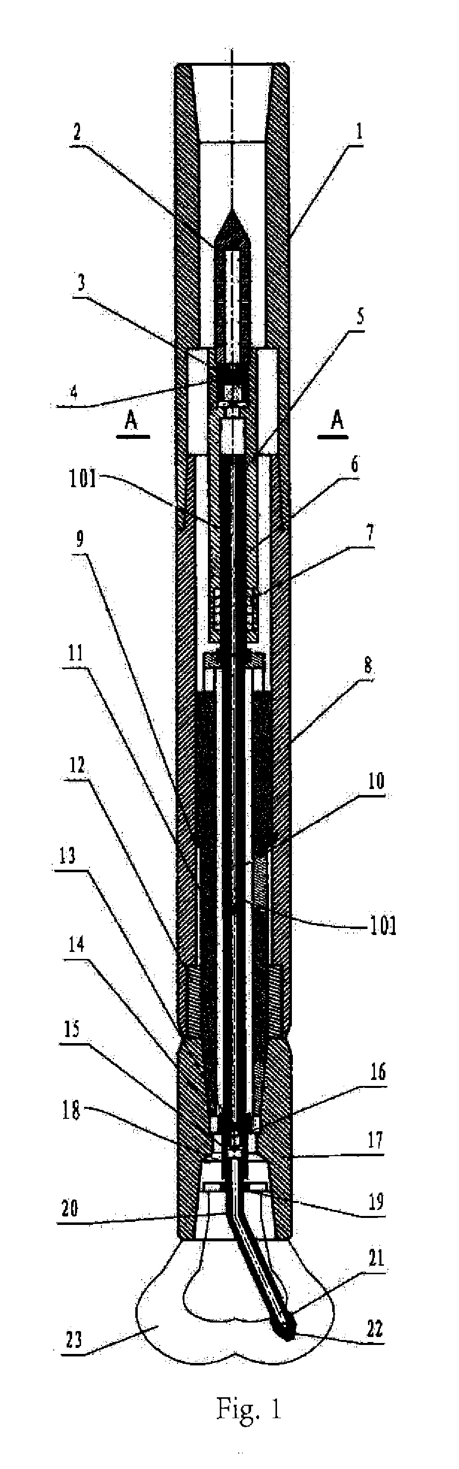
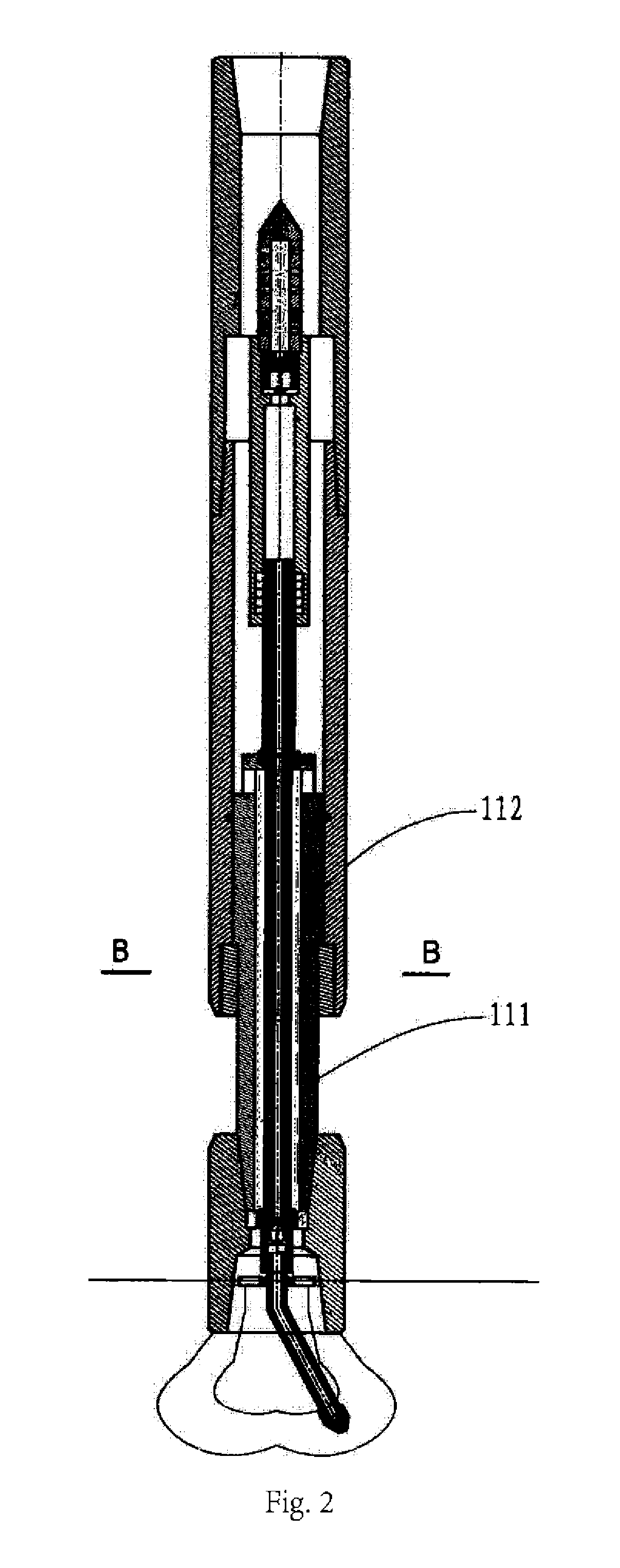
[0028]In order to have a more clear understanding about the technical features, objects and effects of the present invention, the structures, features and effects of the impulse-type underground supercharged jet drilling method and device will be detailedly described as follows with reference to the drawings and preferred embodiments. In addition, through the descriptions of the implementation, the technical means adopted to achieve the intended objects of the present invention and the produced effects will be understood more deeply and concretely. However, the drawings just provide references and illustrations, rather than limitations to the present invention. Moreover, in the drawings, the upper direction is the upper end, and the lower direction is the lower end.

[0029]As illustrated in FIGS. 1 and 2, the impulse-type underground supercharged jet drilling method uses the up and down vibrations of a drill string or the WOB variation during the drilling process, so that an upper joi...


PUM


Abstract

An impulse-type underground supercharged jet drilling method and device is provided. The impulse-type underground supercharged jet drilling method uses up and down vibrations of a drill string or weight on bit variation during the drilling process, so that an upper joint connected to the drill string drives a housing and a supercharging cylinder block to move up and down relative to a supercharging piston, while the supercharging piston, a high pressure line, and a drive shaft disposed outside the high pressure line make a reciprocally retractable movement relative to the housing. As a result, some working fluid entering the supercharging cylinder block is intermittently supercharged, and discharged from a high pressure fluid passage disposed in the supercharging piston and the high pressure line. The present disclosure can effectively perform an underground supercharging to parts of the drilling fluid, thus improving the rock breaking efficiency and the drilling speed.

Description

FIELD OF THE INVENTION[0001]The present invention relates to a hydraulic jet drilling device, and particularly, to an impulse-type underground supercharged jet drilling method and device, which breaks rocks and drills holes by using the vibrations generated during the drilling process.BACKGROUND OF THE INVENTION[0002]With the extension of the borehole in the drilling process, the rocks need to be continuously broken, and usually for a distance of several kilometers. However, with the increase of the well depth, the difficulty of rock breaking increases while the efficiency of rock breaking decreases. The conventional rock breaking methods mainly include the mechanical method and the jet hydraulic one, and the latter requires very high jet pressure.[0003]Under the current drilling conditions, the jet only has an auxiliary function of hydraulic rock breaking. When the jet pressure is increasing, the effect of hydraulic auxiliary rock breaking will be improved, and even rocks may be di...

Claims


Application Information

Patent Timeline
Patent Type & Authority Applications(United States)
IPC IPC(8): E21B7/18
CPCE21B7/18E21B4/006E21B7/24
Inventor LI, GENSHENGNIU, JILEIHUANG, ZHONGWEISHI, HUAIZHONGTIAN, SHOUCENGFU, JIASHENG
Owner CHINA UNIV OF PETROLEUM (BEIJING)
Why Eureka
Try Eureka