System and method for detecting multiple-excitation-induced light in a flow channel

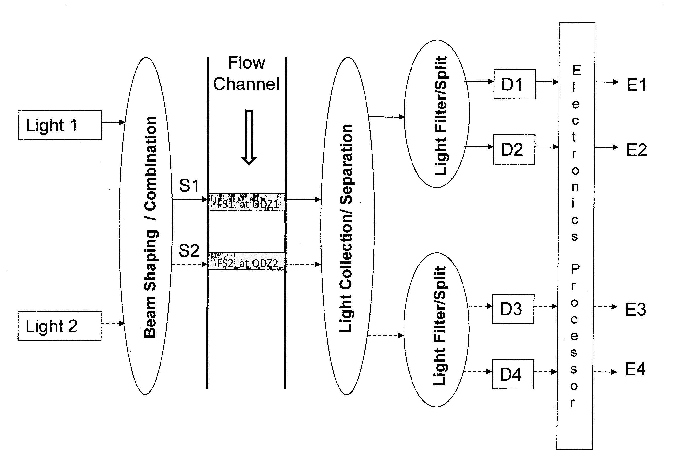
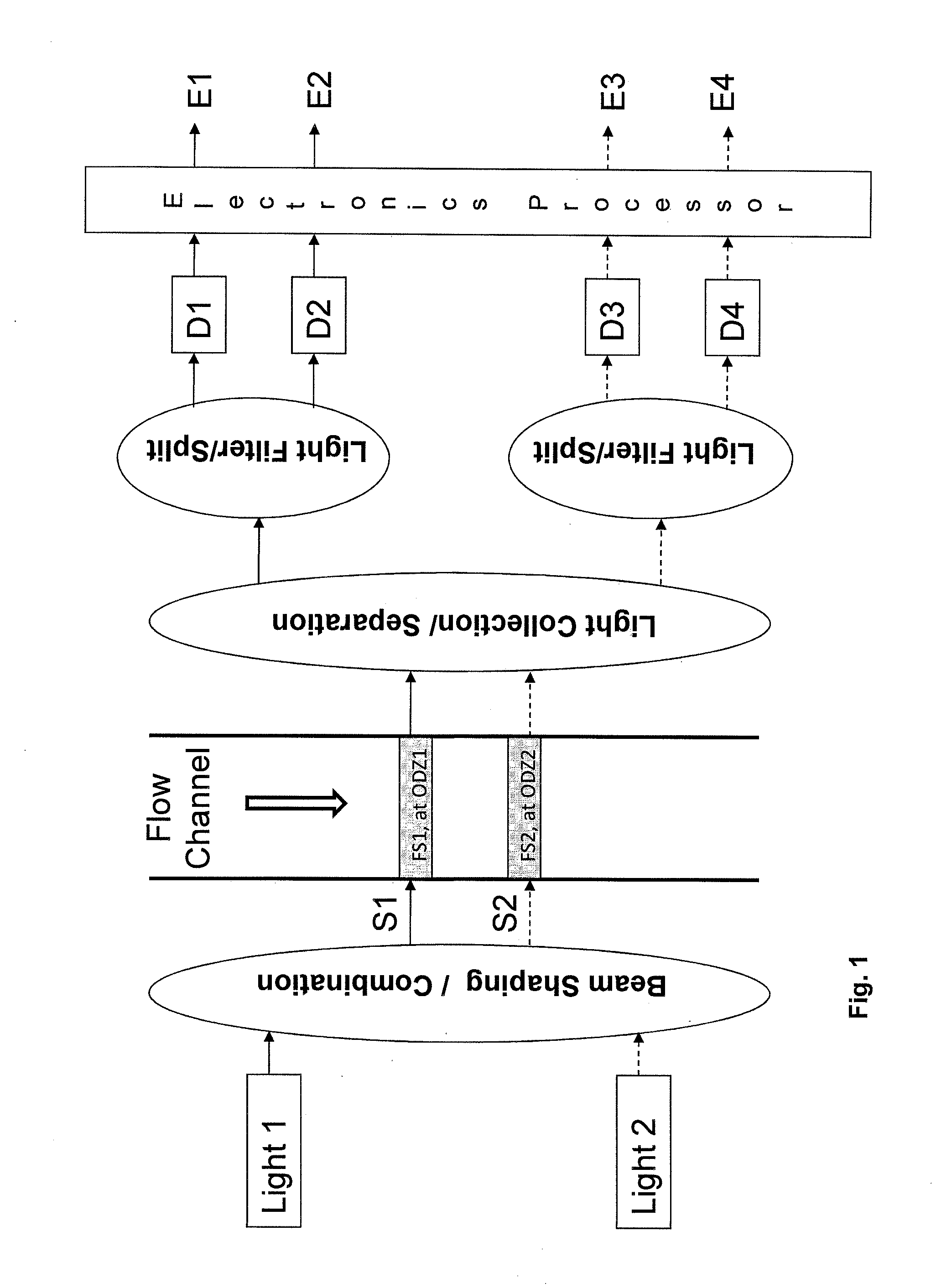
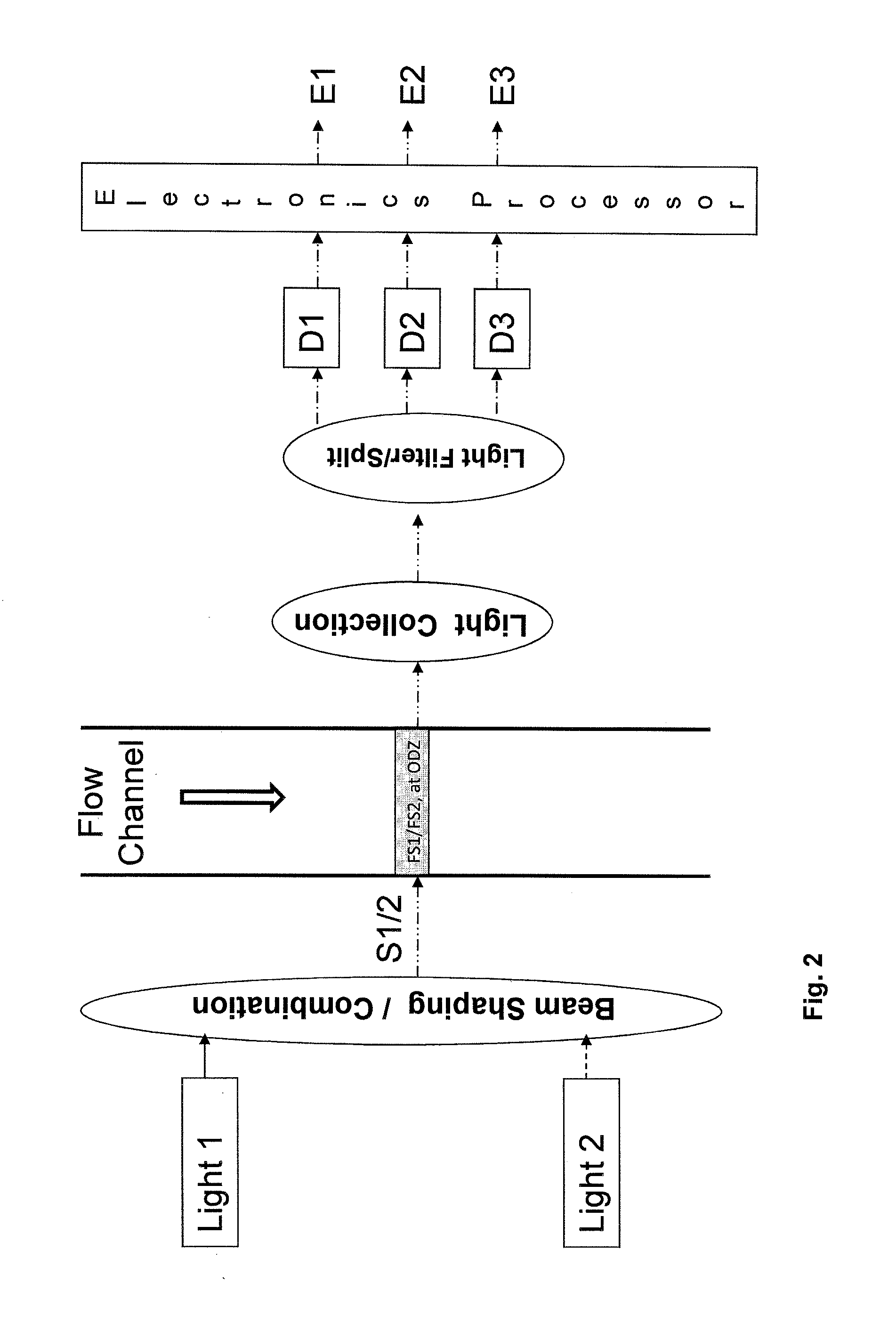
a flow channel and multiple excitation technology, applied in the field of detection light, can solve the problems of unreliability of signal measurement results, first approach has several limitations, and the flexibility of choosing the fluorochrome for cell staining, so as to reduce the complexity of electronic-processor sub-systems, minimize or very low the probability of two particles/cells being both within two oizs, and minimize interference or crosstalk.

Active Publication Date: 2013-08-08
AGILENT TECH INC
View PDF2 Cites 46 Cited by
  • Summary
  • Abstract
  • Description
  • Claims
  • Application Information

AI Technical Summary

Benefits of technology

[0018]A detection sub-system includes light collection optics capable of collecting light emitted from different optical interrogation zones. The collected light is then split or filtered into light of interest with different wavelength ranges and is detected via photodetectors such as PMT (photo-multiplier tubes), APD (avalanche photodiodes) and the like. In the present invention, the emitted light from all the OIZs is collected and then preferably filtered by band-pass filters to split all the collected light into different wavelength ranges. Then a set of corresponding photodetectors convert the light signals into electronic signals and such electronic signals are processed by an electronics processor using methods including amplification, multiplying with a signal, filtering, de-modulation, A / D conversion, signal recovery means, etc. Since at least one excitation light source in the present invention may be modulated, the resulting electronics signal, i.e. particle-induced (or cell-induced) pulse from the photodetector would be correspondingly modulated as well. De-modulation and signal-recovery-means are used to recover these particle-induced pulses and correlate each individual particle-induced pulse to its excitation wavelength. Different de-modulation and signal-recovery-means can be employed, including single-side demodulation, quadrature demodulation and square-wave demodulation. In this way, the filter and photodetector set for detecting the same emission wavelength range can be shared even though the emission light may be excited by different excitation light sources. Therefore, it shows advantages over the first approach in the prior art, as schematically represented in FIG. 1. In addition, there is no strict requirement for the location of optical interrogation zones for effective detection using present invention, as long as the separation distance of the adjacent OIZs are properly selected so that the probability of two particles / cells being both within two OIZs is minimized or very low. Therefore, the change of the separation distance of the OIZs caused by any factors such as temperature, pressure, misalignment during instrument shipping, or other system instability factors, will not affect the measurement results of the signals. Furthermore, as an advantage over the time-multiplexed illumination of multiple excitation light beams in U.S. Pat. No. 7,990,525, the system and method in the present invention do not need for accurate synchronization between the modulations of each excitation light source (i.e., the modulation of each excitation light source is independent of each other).
[0019]In addition, compared with the approaches described in U.S. Pat. No. 8,077,310 where light from different excitation sources emit to the same location on the flow cell, the system and method in the present invention directs light from different excitation sources onto different locations, allowing for the use of full dynamic range of photodetectors for detecting the fluorescent signals caused by each individual light excitation source and minimizing possible interference or crosstalk between fluorescent signals caused by different excitation sources.
[0020]Finally, compared with approaches described in US 2007 / 0096039 and US 2008 / 0213915 where multiple excitation light sources are all modulated with each source being modulated at different frequencies, the system and method in the present invention require that at least one light source is not modulated. In addition, when multiple light sources are intensity-modulated, their modulation frequencies are preferably to be the same. These approaches offer significant advantages in reducing the complexity of electronic-processor sub-systems and in improving the system performance such as signal-to-noise ratio, signal process flow as well as data analysis and process speed.

Problems solved by technology

Otherwise, the flexibility of choosing the fluorochrome for cell staining would be limited and it becomes a shortcoming for a flow cytometer.
However, the first approach has several limitations.
If the separation distance between these OIZs varies due to any factors such as temperature, pressure, misalignment during instrument shipping, or other system instability factors, it may affect not only the time interval between detected pulses generated in two OIZs but also, more importantly, the efficiency of light collection for each OIZ, leading to unreliable measurement results of the signals.
(3) The optical setup is not efficient because each photodetector is used to detect only one type of fluorescent molecule (i.e. having a pre-determined excitation wavelength and emission bandwidth).
Combining of the detection of FM2 and FM4 with one band-pass filter and one photodetector is not possible in this configuration.
This results in the increased complexity and therefore increased cost of the whole system.
On the other hand, this approach has a major limitation that it could not distinguish the fluorescent signals from different fluorescent molecules having the same emission spectra even if they are excited by different lasers.
However, this approach possessed other limitations.
Furthermore, such issue would become more severe especially when the number of the excitation light sources increases.
However, due to stray current of the electronic signal for the digital modulation of the laser source and / or the property of the laser source (i.e. modulation ratio is not high enough so that there is still low level of light from the light source even when it is controlled to be OFF), such OFF-status light source will still contribute some illumination to the OIZ thus increase the background for detection and measurement of the emitted fluorescent signal excited by another ON-status light source, affecting the system sensitivity for detecting low-level, dim fluorescent particles / cells.
However, such an approach has limitations due to emitting multiple excitation sources onto a single location on the flow cell and simultaneous turn-on of multiple excitation sources at some time moments.
These approaches have limitations associated with the requirement of modulation of all excitation sources at unique frequencies and the ineffectiveness in the de-modulation methods in achieving high signal-noise ratios.

Method used


Image

  • System and method for detecting multiple-excitation-induced light in a flow channel
  • System and method for detecting multiple-excitation-induced light in a flow channel
  • System and method for detecting multiple-excitation-induced light in a flow channel

Examples


example 1

Two Intensity-Modulated Light Sources

[0054]Below we will discuss some examples of modulation and de-modulation methods. For example, light beam directed to OIZ1 is modulated by a sine-wave signal at a frequency f1 and phase value zero (i.e. Mod1=sin(2πf1t)+1) and light beam directed to OIZ2 is modulated by a sine-wave signal at a frequency f2 and a phase value φ2(i.e. Mod2=sin(2πf2t+φ2)+1)). The first modulation signal Mod1 has a phase value of zero and its phase is used as a reference for all signals in the system. Thus, the second modulation signal Mod2 has a phase value of φ2. Total electronic signals Total_Signal from a photodetector is the sum of the signal associated with emitted light from OIZ1 (Sig1) and OIZ2 (Sig2), respectively, and can be expressed as,

TotalSignal=Sig1+Sig2=S1(t)(sin(2πf1t+ϕ3)+1)+S2(t)(sin(2πf2t+ϕ4)+1)(1)

where S1(t) and S2(t) are output electronic signal from the photodetector due to particles / cells passing through the 1st OIZ and the 2nd OIZ, respectively...

example 2

One Intensity-Modulated Light Source and One Non-Modulated Light Source

[0067]In above sections, both light beams are modulated and single-component de-modulation and quadrature demodulation methods are used to recover corresponding electronic pulse profiles from the modulated signals. In following examples, we consider the cases where one light beam is not modulated and modulation is applied to the other light beams. We perform exemplary analysis for the case of two excitation sources where light beam directed to OIZ1 is modulated by a sine-wave signal at a frequency f1 and phase value zero (Mod1=sin(2πf1t)+1) and light beam directed to OIZ2 is not modulated. Total electronic signals Total_Signal from a photodetector is the sum of the signal associated with emitted light from OIZ1 (Sig1) and OIZ2 (Sig2), respectively, and can be expressed as,

Total_Signal=Sig1+Sig2=S1(t)(sin(2πf1t+φ3)+1)+S2(t)  (8)

where S1(t) and S2(t) are output electronic signal from the photodetector due to partic...

example 3

Two Intensity-Modulated Light Sources at Same Modulation Frequency and Different Modulation Phases

[0078]In above examples, modulation applied to different light sources has been based on differences in modulation frequency (f1 and f2 in equation (1)) and in amplitude (1 for modulation S1(t) and 0 for S2(t) in equation (8)). Modulation of different light sources could also be based on phase angles of the modulation signals but with the same modulation frequency. Light beam directed to OIZ1 is modulated by a sine-wave signal at a frequency f1 with phase angle 0 (i.e. Mod1=sin(2πf1t)+1) and light beam directed to OIZ2 is modulated by a sine-wave signal at the same frequency f1 but with a phase angle θ (i.e. Mod2=sin(2πf1t+θ)+1). Total_Signal from a photodetector is the sum of the signal associated with emitted light from OIZ1 (Sig1) and OIZ2 (Sig2), respectively, and can be expressed as,

Total_Signal=Sig1+Sig2=S1(t)(sin(2πf1t)+1)+S2(t)(sin(2πf1t+θ)+1)  (13)

where S1(t) and S2(t) are outp...


PUM

PropertyMeasurementUnit
wavelengthsaaaaaaaaaa

Abstract

A system for detecting signal components of light induced by multiple excitation sources including: a flow channel including at least two spatially separated optical interrogation zones; a non-modulating excitation source that directs a light beam of a first wavelength at a near constant intensity onto a first of the optical interrogation zones; a modulating excitation source that directs a light beam of a second wavelength with an intensity modulated over time at a modulating frequency onto a second of the optical interrogation zones; a detector subsystem comprising a set of detectors configured to detect light emitted from particles flowing through the at least two optical interrogation zones and to convert the detected light into a total electrical signal; and a processor that determines signal components from the light detected from each of the optical interrogation zones.

Description

CROSS REFERENCE TO RELATED APPLICATIONS[0001]This application claims benefit of priority to U.S. provisional patent application Ser. No. 61 / 550,243, filed Oct. 21, 2011; the contents of which are herein incorporated by reference in their entirety.TECHNICAL FIELD[0002]This invention relates generally to the field of detecting light emitted from fluorescent molecules excited by multiple excitation light sources, and more specifically to a system and method that incorporates at least one intensity modulated excitation light source and a nonmodulated light source to induce the emission of light from at least two spatially separated optical interrogation zones of a flow channel and the detection and measurement thereof.BACKGROUND OF THE INVENTION[0003]Flow cytometer is an instrument for measuring / analyzing individual fluorescently-labeled particles / cells being lined up and flown through a flow channel under hydrodynamic focusing or other focusing forces. Light beam from individual light ...

Claims


Application Information

Patent Timeline
Patent Type & Authority Applications(United States)
IPC IPC(8): G01N21/64
CPCG01N21/64G01N21/6428G01N21/645G01N2021/6419G01N2021/6421G01N2021/6441G01N15/1434G01N2015/1438G01N15/1429G01N2015/1006G01N2015/149G01N15/1459G01N2021/6482G01N2201/06113G01N2201/0621
Inventor LI, NANWU, JIANCHEN, YEWANG, TIANXINGWANG, XIAOBO
Owner AGILENT TECH INC
Why Eureka
Try Eureka