Motor control device, current control method applied to motor control device, and electric power steering device using motor control device

Active Publication Date: 2013-08-08
MITSUBISHI ELECTRIC CORP
View PDF10 Cites 65 Cited by
  • Summary
  • Abstract
  • Description
  • Claims
  • Application Information

AI Technical Summary

Benefits of technology

[0014]According to the motor control device, the current control method applied to a motor control device, and the electric power steering device using a motor control device of the present invention, there is provided means for detecting the secondary failure by a failure detection method depending on the primary failure state. Therefore, it is possible to provide the motor control device, the current control method applied to a motor control device, and the electric power steering device using a motor control device, which are capable of, in a case where a failure of a winding of a

Problems solved by technology

When a failure occurs on a winding or an inverter on one side, the motor control device opens a power supply relay for the side on which the failure has occurred, thereby interrupting the connection to the power supply.
However, the conventional technology has the following problems.
However, when a short-circuit failure occurs, a closed circuit through a portion of the short-circuit failure and a windings is formed, resulting in a circulating current that does not flow through the power supply.
Accordingly, there occurs a problem of a lack of

Method used


Image

  • Motor control device, current control method applied to motor control device, and electric power steering device using motor control device
  • Motor control device, current control method applied to motor control device, and electric power steering device using motor control device
  • Motor control device, current control method applied to motor control device, and electric power steering device using motor control device

Examples


first embodiment

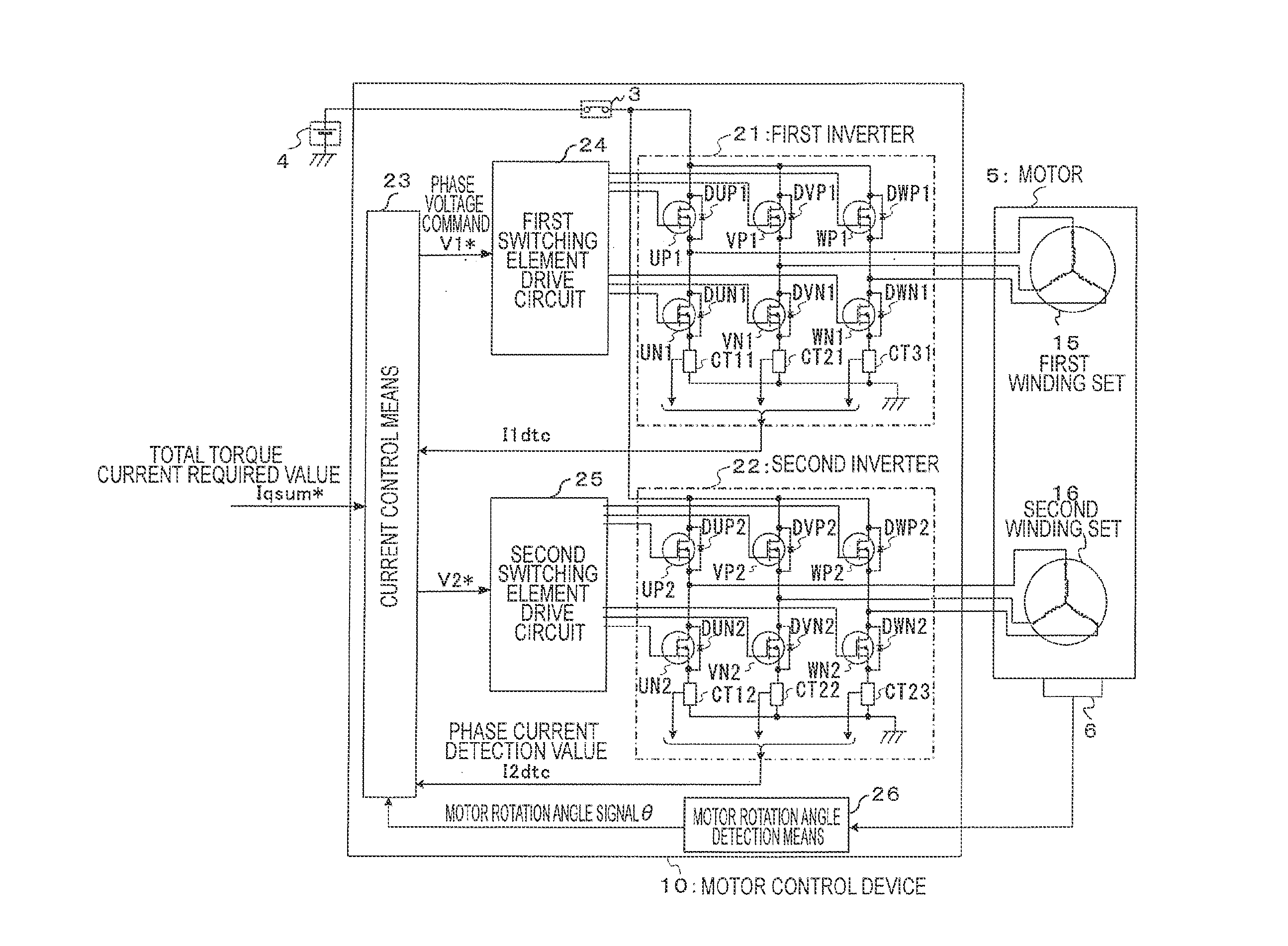
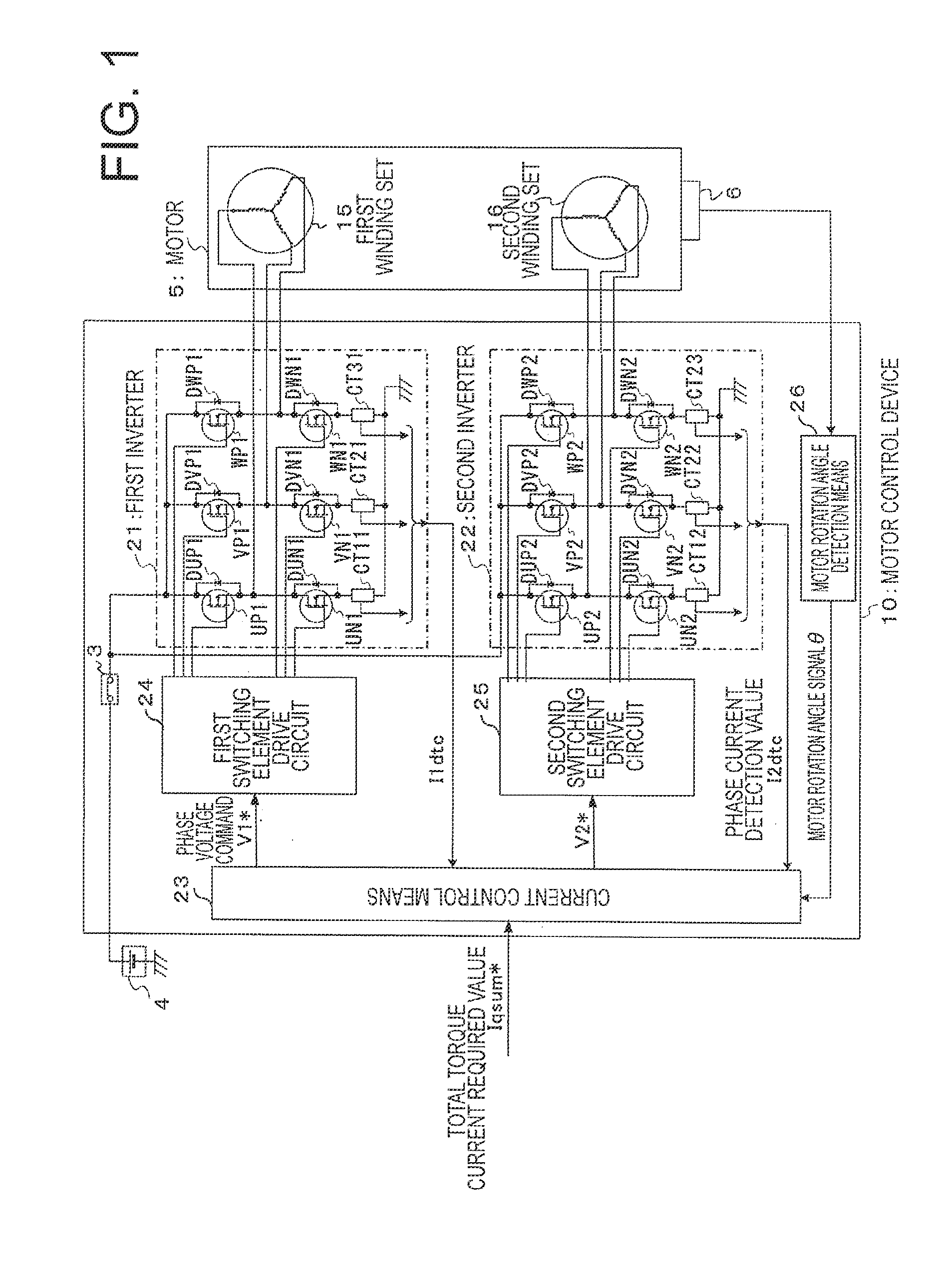
[0028]FIG. 1 is a schematic block diagram illustrating an overall configuration including a motor control device according to a first embodiment of the present invention. Note that, FIG. 1 illustrates a power supply 4, a motor 5, and a motor rotation angle sensor 6 for detecting a rotation angle of the motor 5 in addition to the motor control device 10.

[0029]The motor 5 includes a first winding set 15 constituted by three phases, U1, V1, and W1, and a second winding set 16 constituted by three phases, U2, V2, and W2. Then, the each of the winding sets 15 and 16 connects the phases as the star connection. Those plurality of winding sets 15 and 16 constitute a stator (not shown). The motor 5 is constituted by this stator, and a rotor and a rotation shaft fixed to the rotor, which are not shown.

[0030]Note that, in the following, a description is given of an example in which the present invention is applied to a permanent-magnet synchronous motor in which each of the winding sets has th...


PUM


Abstract

Provided is a motor control device (10) for controlling a motor (5) provided with a plurality of sets of windings, in which, when a current control unit (23) detects a short-circuit failure as a primary failure, the current control unit (23) continues the control, and, further, when the current control unit (23) detects a secondary failure, the current control unit (23) provides control of opening a power supply relay (3). Accordingly, in a case where a failure of a winding of a motor or an inverter occurs, a torque pulsation is restrained and a sufficient output torque is provided, and further, in a case where a secondary failure occurs, excessive heat generation and current consumption are prevented and the cost of the device is reduced.

Description

BACKGROUND OF THE INVENTION[0001]1. Field of the Invention[0002]The present invention relates to a motor control device for controlling a multi-phase motor including a plurality of sets of windings, a current control method applied to a motor control device, and an electric power steering device using a motor control device.[0003]2. Description of the Related Art[0004]As a motor control device for controlling a conventional multi-phase motor including a plurality of sets of windings, there is a motor control device having a configuration in which a motor includes two sets of windings, and the motor control device includes two inverters for controlling currents flowing through the respective sets of windings, thereby independently controlling the currents (for example, refer to Japanese Patent Application Laid-open No. 2011-131860).[0005]The motor control device according to Japanese Patent Application Laid-open No. 2011-131860 includes, in order to supply respective inverters with p...

Claims


Application Information

Patent Timeline
IPC IPC(8): H02P6/12
CPCH02P25/22H02P29/021H02P27/06B62D5/0403B62D5/0487H02P29/0241
Inventor KEZOBO, ISAONAKANO, KOSUKEASAO, YOSHIHITO
Owner MITSUBISHI ELECTRIC CORP
Why Eureka
Try Eureka