
Organism state quantity measuring apparatus

a technology of quantity measurement and organs, applied in the field of organs state quantity measurement apparatus, can solve problems such as difficulty in obtaining an accurate measured output valu

Inactive Publication Date: 2013-08-08
OLYMPUS CORP
View PDF8 Cites 4 Cited by
  • Summary
  • Abstract
  • Description
  • Claims
  • Application Information

AI Technical Summary

Benefits of technology

The patent text is explaining that certain characteristics of circuit elements in an integration circuit, such as electrostatic capacitance and resistance value, can change over time and with the environment. This can cause difficulty in accurately measuring output from the circuit. The patent aims to address this problem.

Problems solved by technology

At that time, in the case of the apparatus according to Japanese Patent No. 3683856, the output from the integration circuit changes with changes in characteristic values of the circuit elements and it is difficult to obtain an accurate measured output value.

Method used


Image

  • Organism state quantity measuring apparatus
  • Organism state quantity measuring apparatus
  • Organism state quantity measuring apparatus

Examples


first embodiment

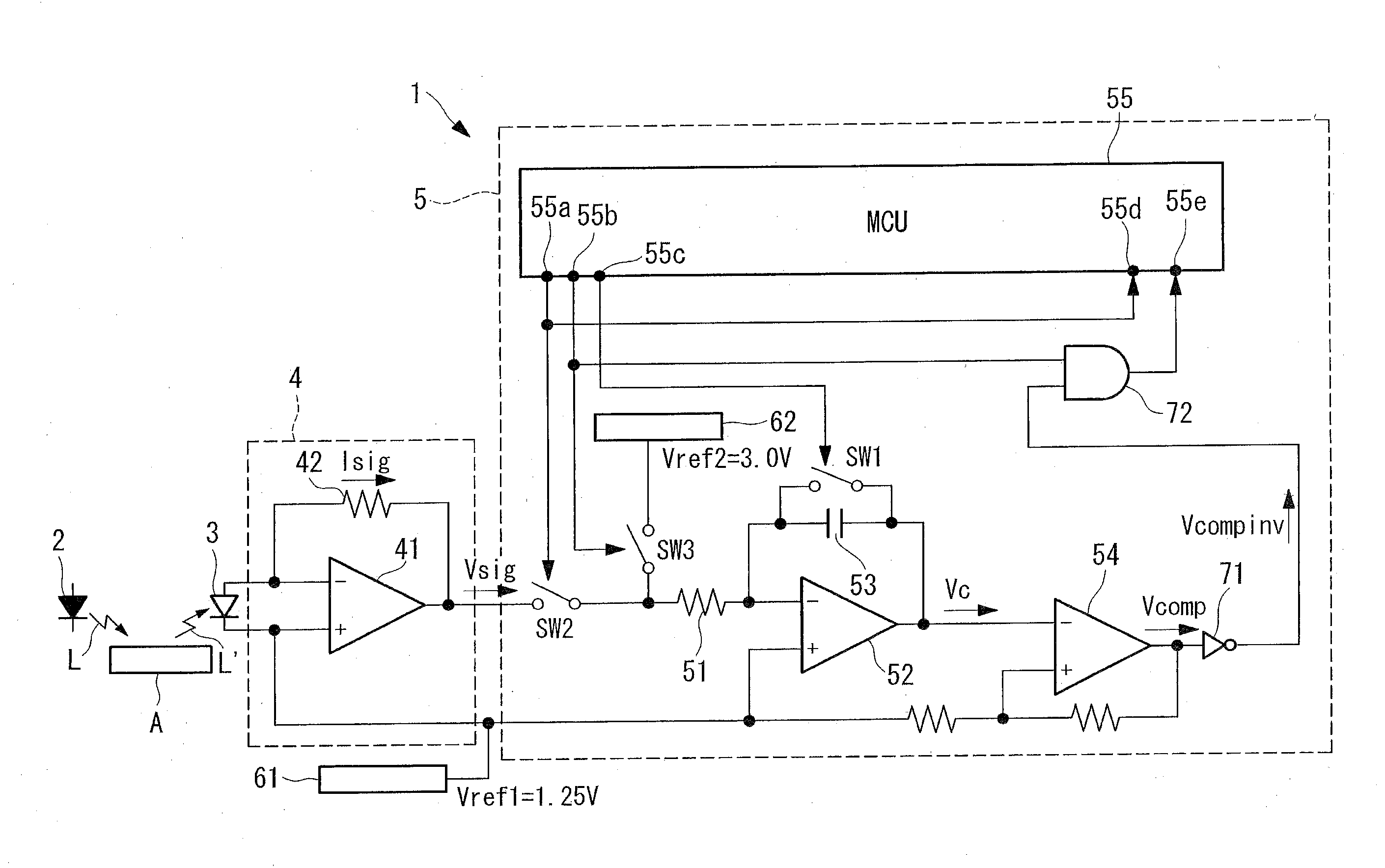
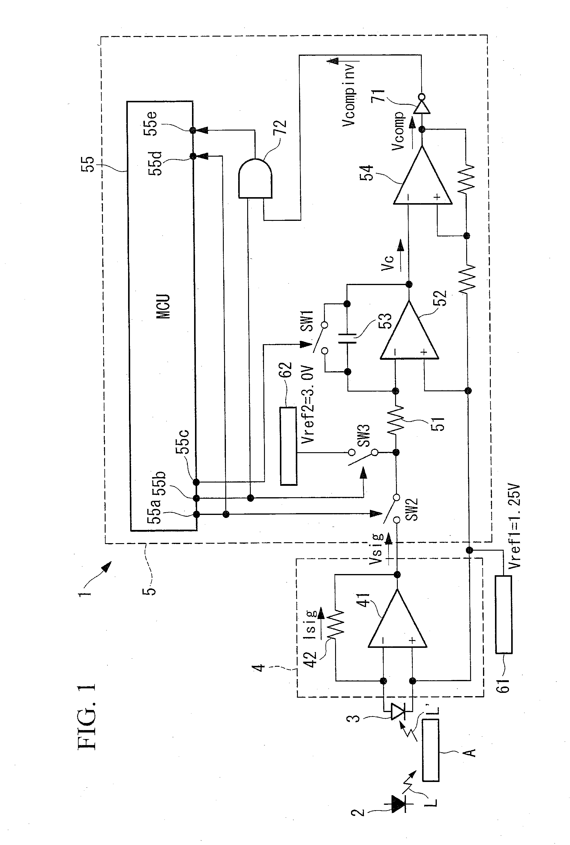
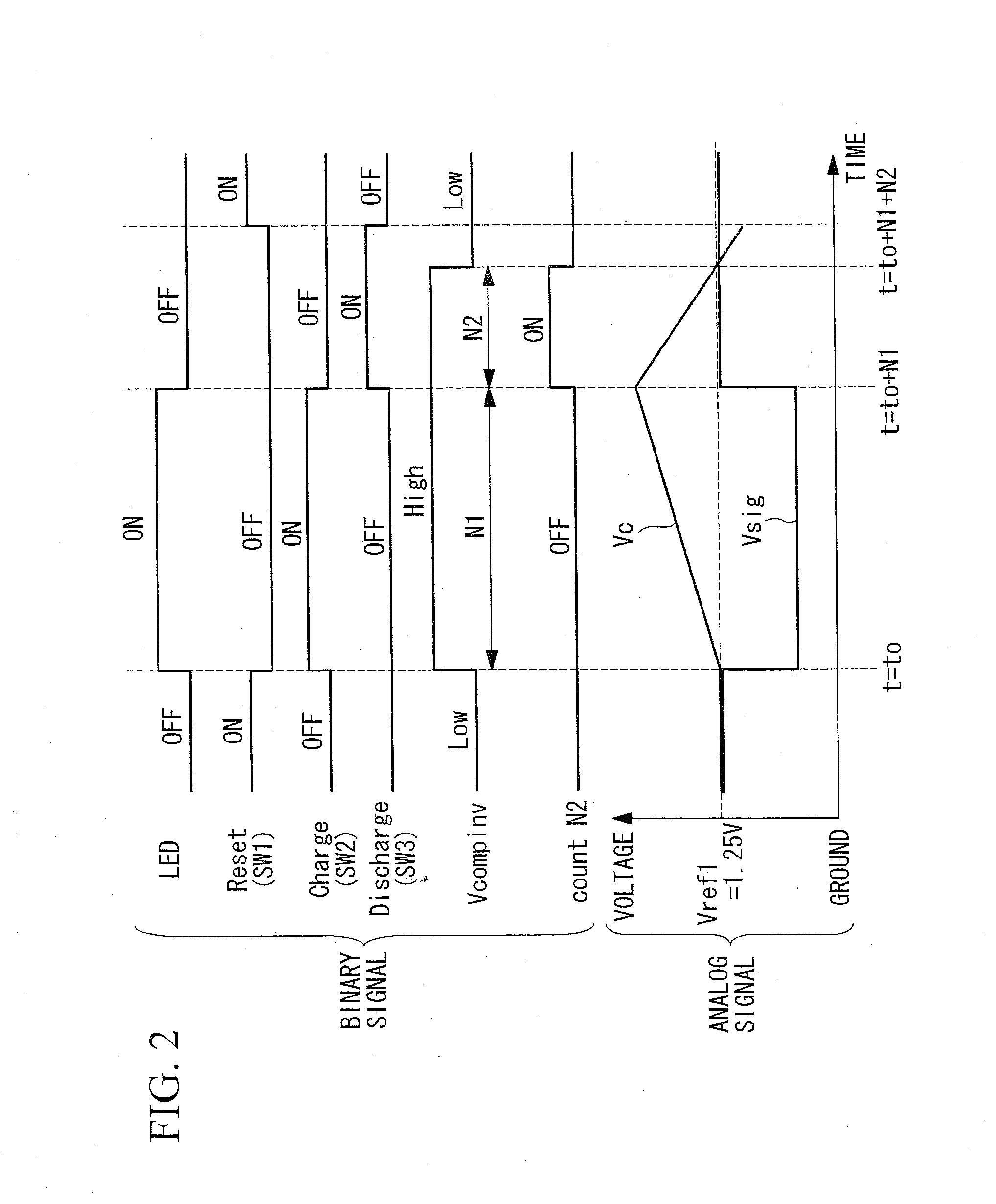
[0015]An organism quantity measuring apparatus 1 according a first embodiment of the present invention will be described below with reference to FIGS. 1 and 2.

[0016]As shown in FIG. 1, the organism quantity measuring apparatus 1 according the present embodiment has a light emitting diode (an LED, a detecting unit or an illumination light source) 2 that applies illumination light L to an organism or an organism specimen A extracted from an organism (hereinafter referred to as “organism or the like”), a photodiode (a PD or a detecting unit) 3 that detects signal light L′ from the organism or the like A, a current-voltage conversion circuit (IV conversion circuit) 4 that converts a signal current Isig from the PD 3 into a signal voltage Vsig, and an A / D conversion circuit 5 of a double integration type that calculates a state quantity of the organism based on the signal voltage Vsig from the IV conversion circuit 4.

[0017]The LED 2 applies illumination light L, for example, to blood or ...

second embodiment

[0044]An organism state quantity measuring apparatus 1 according to a second embodiment of the present invention will be described with reference to FIGS. 3 to 6.

[0045]Description will be made mainly of the points of difference of the second embodiment from the above-described first embodiment. The components that the second embodiment and the first embodiment have in common are indicated by the same reference numerals and the description for them will not be repeated.

[0046]The organism state quantity measuring apparatus 1 according to the present embodiment differs from that according to the first embodiment in that, as shown in FIG. 3, different reference voltages Vref1 and Vref3 are respectively applied to the integration operational amplifier 52 and the IV operational amplifier 41.

[0047]The integration operational amplifier 52 has the first reference voltage Vref1 applied to its plus input terminal, as does that in the first embodiment.

[0048]The IV operational amplifier 41 has t...


PUM


Abstract

An apparatus including a detecting unit that detects information indicating a state of an organism from the organism or an organism specimen extracted from the organism and outputs the detected information as a current, a current-voltage conversion circuit that converts the current output from the detecting unit into a voltage, a double-integration-type A / D conversion circuit having an integration capacitor that is charged based on a voltage output from the current-voltage conversion circuit and is thereafter discharged, and a counter that measures a charge time during which the integration capacitor is charged and a discharge time during which the integration capacitor is discharged, the A / D conversion circuit converting into digital quantities the charge time and the discharge time measured by the counter, and outputting the digital quantities, and an information processing unit that calculates a state quantity of the organism based on the digital quantities output from the A / D conversion circuit.

Description

CROSS-REFERENCE TO RELATED APPLICATION[0001]This is a continuation of International Application PCT / JP2011 / 055793, with an international filing date of Mar. 11, 2011, which is hereby incorporated by reference herein in its entirety.BACKGROUND OF THE INVENTION[0002]1. Field of the Invention[0003]The present invention relates to an organism state quantity measuring apparatus.[0004]2. Description of Related Art[0005]Among apparatuses for injecting insulin into an organism, an apparatus is conventionally known that measures the glucose level in an organism and controls the amount of injection of insulin according to the measured value obtained (see, for example, the publication of Japanese Patent No. 3683856). An analog signal for the measured glucose level is converted into a digital signal by an A / D converter having an integration circuit, and the digital signal is processed.[0006]However, Characteristic values such as an electrostatic capacitance and a resistance value of circuit ele...

Claims


Application Information

Patent Timeline
Patent Type & Authority Applications(United States)
IPC IPC(8): H03M1/52
CPCA61B5/14532H03M1/52G01N21/6428A61B5/1459
Inventor SUGIMOTO, NAOYA
Owner OLYMPUS CORP
Learn More