Pressure Detection Unit and Information Input Device Having the Pressure Detection Unit

a technology of pressure detection unit and information input device, which is applied in the direction of instruments, computing, electric digital data processing, etc., can solve the problems of irregular sensitivity inability to contact between the pressure sensitive ink layer, etc., to improve the detection characteristics, increase the press operation area of the panel, and reduce the area of the pressure detection unit

Inactive Publication Date: 2013-08-08
NISSHA PRINTING COMPANY
View PDF1 Cites 7 Cited by
  • Summary
  • Abstract
  • Description
  • Claims
  • Application Information

AI Technical Summary

Benefits of technology

[0040]With the above arrangement, with the pressure detection unit having improved detection characteristics, information input by a press operation to a panel member in the information input device can be effected in a stable manner. Further, since the pressure detection unit is configured such that the first

Problems solved by technology

This results in instability in the condition of contact between the pressure sensitive ink layer 23a and the electrode

Method used


Image

  • Pressure Detection Unit and Information Input Device Having the Pressure Detection Unit
  • Pressure Detection Unit and Information Input Device Having the Pressure Detection Unit
  • Pressure Detection Unit and Information Input Device Having the Pressure Detection Unit

Examples


embodiment 1

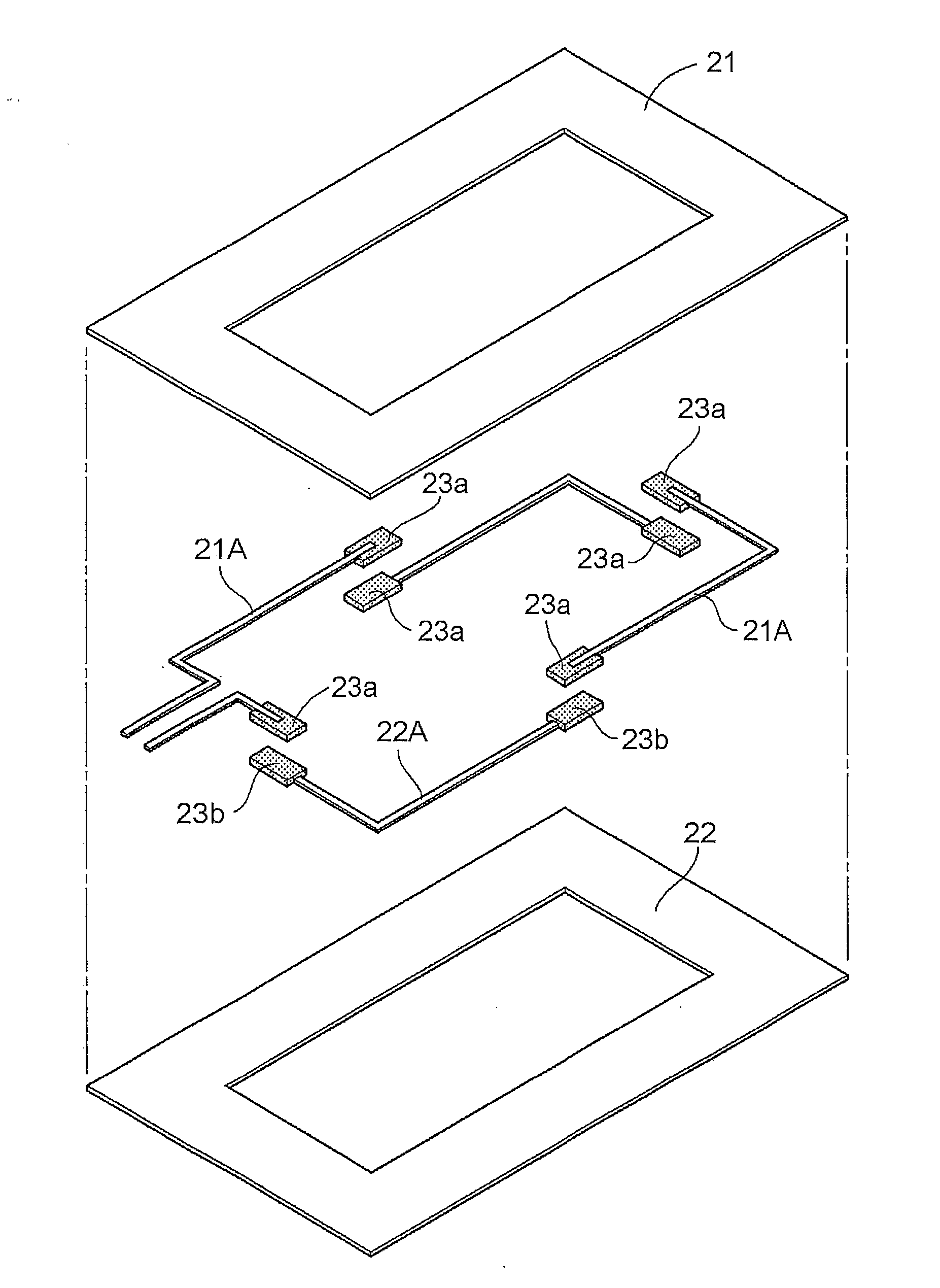
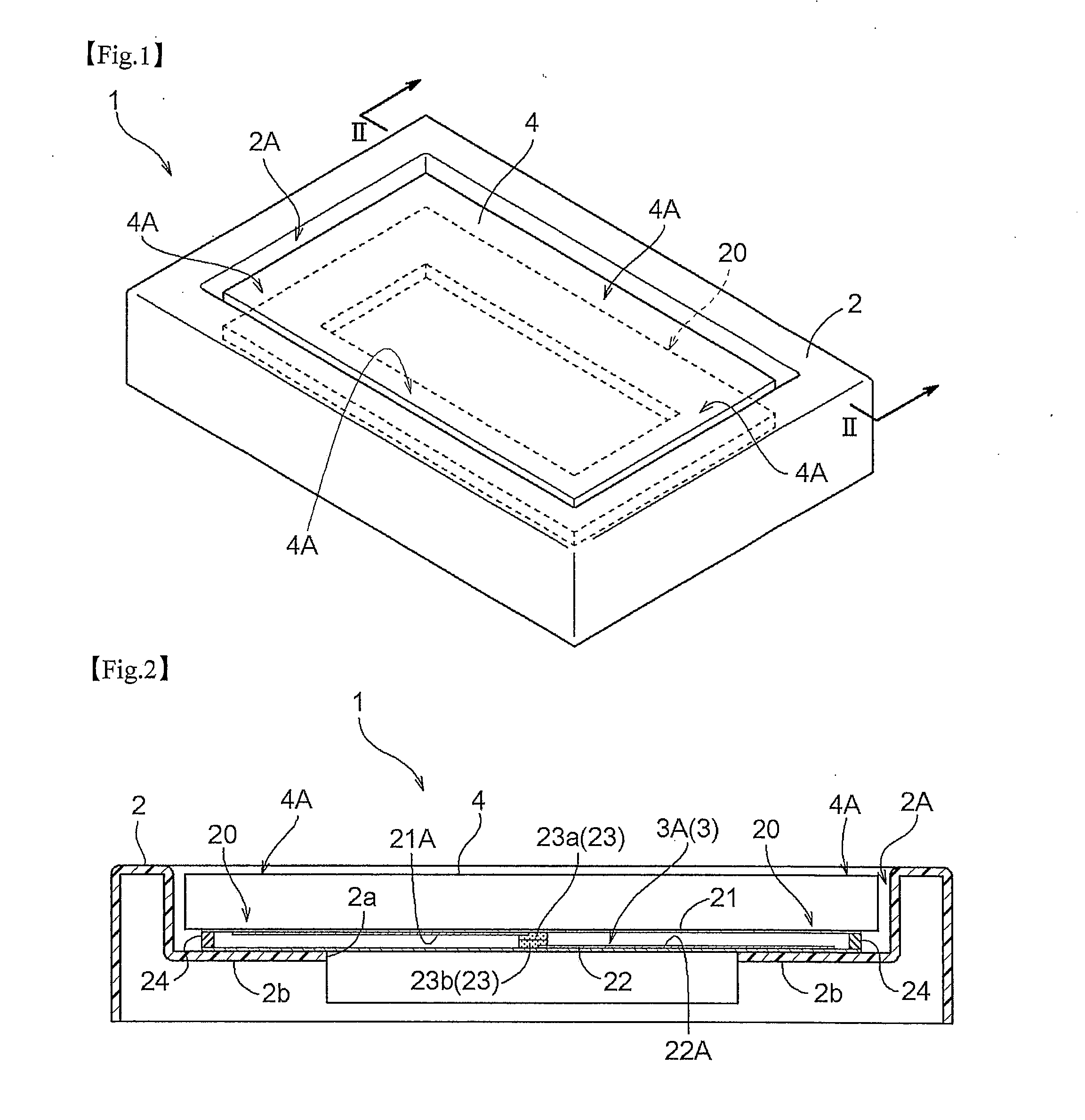
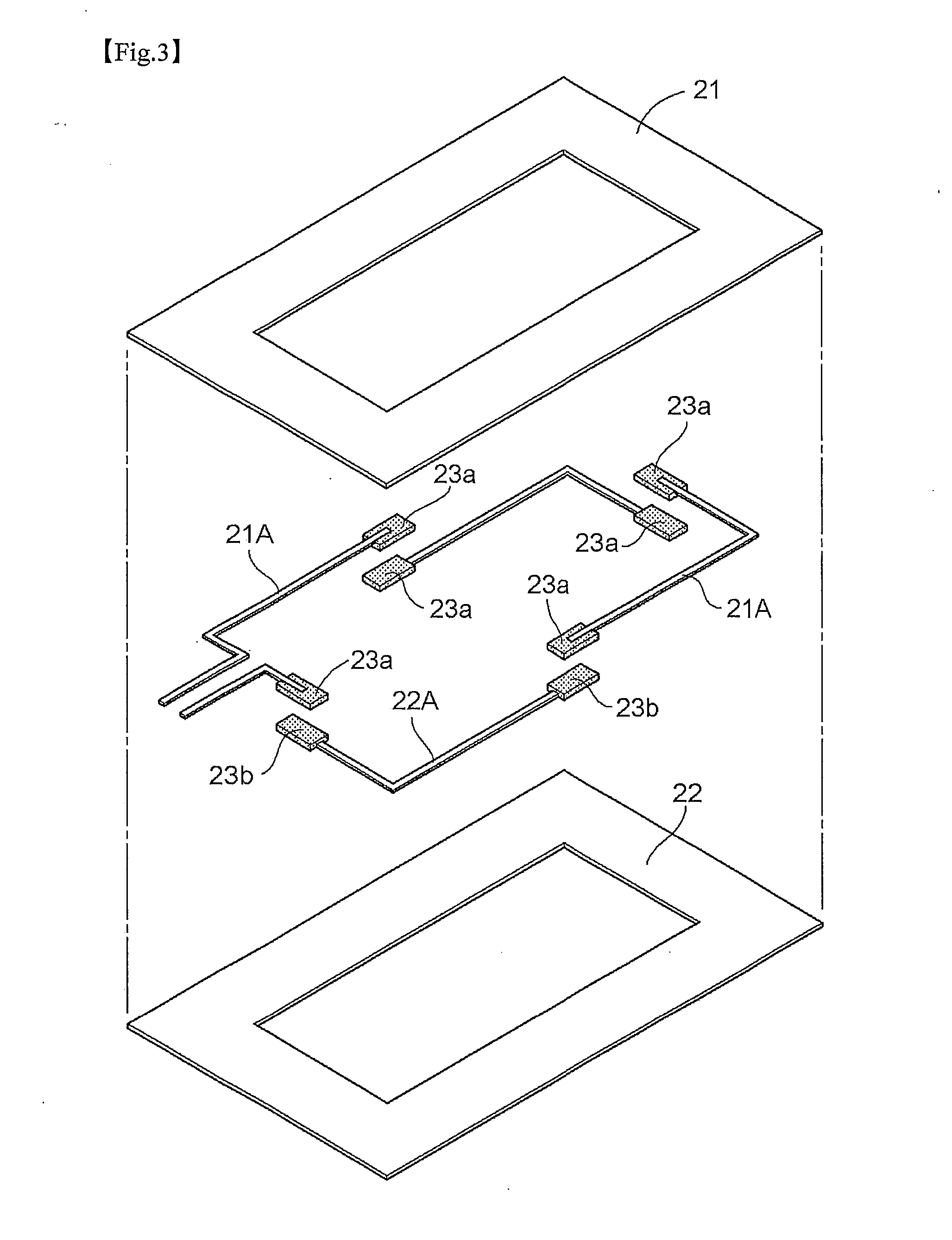
[0068]As shown in FIG. 1 and FIG. 2, an information input device 1 includes a housing body 2 forming an opening 2A or the like in its front face which mounts therein a display device 3 having a display portion 3A formed of liquid crystal, organic EL, etc. and mounts also a panel member 4 having a touch type information input function.

[0069]In the present invention, the opening 2A of the housing body 2, as shown in FIG. 2, is formed by cutting out the upper face of the housing body 2 so as to form a step for allowing fitting-in of the panel member 4. And, on the bottom face thereof, there are provided a display device opening 2a for exposing the display portion 3A of the display device 3 mounted inside the housing body 2 to the outside, and a frame-like support portion 2b for supporting a peripheral portion 4A of the panel member 4.

[0070]The shape and size of the opening 2A can vary in many ways, in accordance with the shape and size of the panel member 4. Further, the mounting depth...

embodiment 2

[0084]In this embodiment, as shown in FIG. 6, the first electrode 21A disposed on the first substrate 21 is coated or covered with a first electrically conductive layer 21B. On the other hand, the second electrode 22A disposed on the second substrate 22 is coated or covered with a second electrically conductive layer 22B. Further, the second electrically conductive layer 22B is coated with the pressure sensitive ink layer 23a as the pressure sensitive layer 23.

[0085]The surface of the pressure sensitive ink layer 23a coating the second electrically conductive layer 22B faces the first electrically conductive layer 21B. Therefore, when the pressure detection unit 20 is pressed by the panel member 4, there is formed, between the second electrode 22 and the second electrically conductive layer 22B, an area (pressure sensitive area) Z where the pressure sensitive layers 23 are compressed. Here, the second electrode 22A is disposed at a position outside the pressure sensitive area Z (tha...

embodiment 3

[0087]In the instant embodiment, as shown in FIG. 7 and FIG. 8, the pressure detection unit 20 is configured such that the first electrically conductive layer 21B is coated or covered with a pressure sensitive layer 23. The pressure sensitive area Z of the pressure sensitive layer 23 is located between the first electrically conductive layer 21B and the second electrically conductive layer 22B and the first electrode 21A is provided at a position not overlapped with the pressure sensitive area Z in the direction along the first substrate 21. In the pressure detection unit 20, on the outer face of the second substrate 22, there is provided a bump 25a which contacts with the support portion 2b as a load transmission member 25 for applying a concentrated load to the pressure sensitive layer 23. The bump 25a is disposed to be overlapped with the pressure sensitive area Z, such that when a load is applied to the pressure detection unit 20 from the panel member 4, the bump 25a supports th...


PUM


Abstract

A pressure detection unit is disposed in a peripheral portion of a panel member of an information input device for detecting a press operation to the panel member. The pressure detection unit includes a first substrate, a second substrate disposed to face the first substrate, a pressure sensitive layer disposed between the first substrate and the second substrate, and a first electrode provided on the first substrate and a second electrode provided on the second substrate for detecting resistance change via the pressure sensitive layer, the first electrode and the second electrode being provided at positions not facing each other along normal lines of the first substrate and the second substrate. The first electrode, the second electrode and the pressure sensitive layer together form a series circuit in the form of a loop.

Description

TECHNICAL FIELD[0001]The present invention relates to a pressure detection unit for an information input device enabling input of information through detection of a press operation to a panel member and relates also to the information input device having the pressure detection unit.BACKGROUND ART[0002]As an information input device including a panel member having an information input function, a device having a touch panel disposed on a liquid crystal display is being widely used. In the case of a digital camera having a liquid crystal monitor, there is known one configured such that on an upper face of the liquid crystal monitor there is disposed a panel member capable of detecting a contact position and a press force, so that in accordance with the strengths of the press at the time of contact, different instructions are given (see e.g. Patent Document 1, FIG. 25).[0003]In a pressure detection unit 20 to be mounted on the information input device described above, for example, as s...

Claims


Application Information

Patent Timeline
IPC IPC(8): G06F3/045
CPCG06F3/03547G06F3/045G06F3/0414
Inventor SUZUKI, TAKAHIROKAI, YOSHIHIROENDO, YUKOHIRAI, SEIKO
Owner NISSHA PRINTING COMPANY
Why Eureka
Try Eureka