
Lithographic apparatus, device manufacturing method, and device manufactured thereby

Active Publication Date: 2005-06-14
ASML NETHERLANDS BV
View PDF8 Cites 4 Cited by
  • Summary
  • Abstract
  • Description
  • Claims
  • Application Information

AI Technical Summary

Benefits of technology

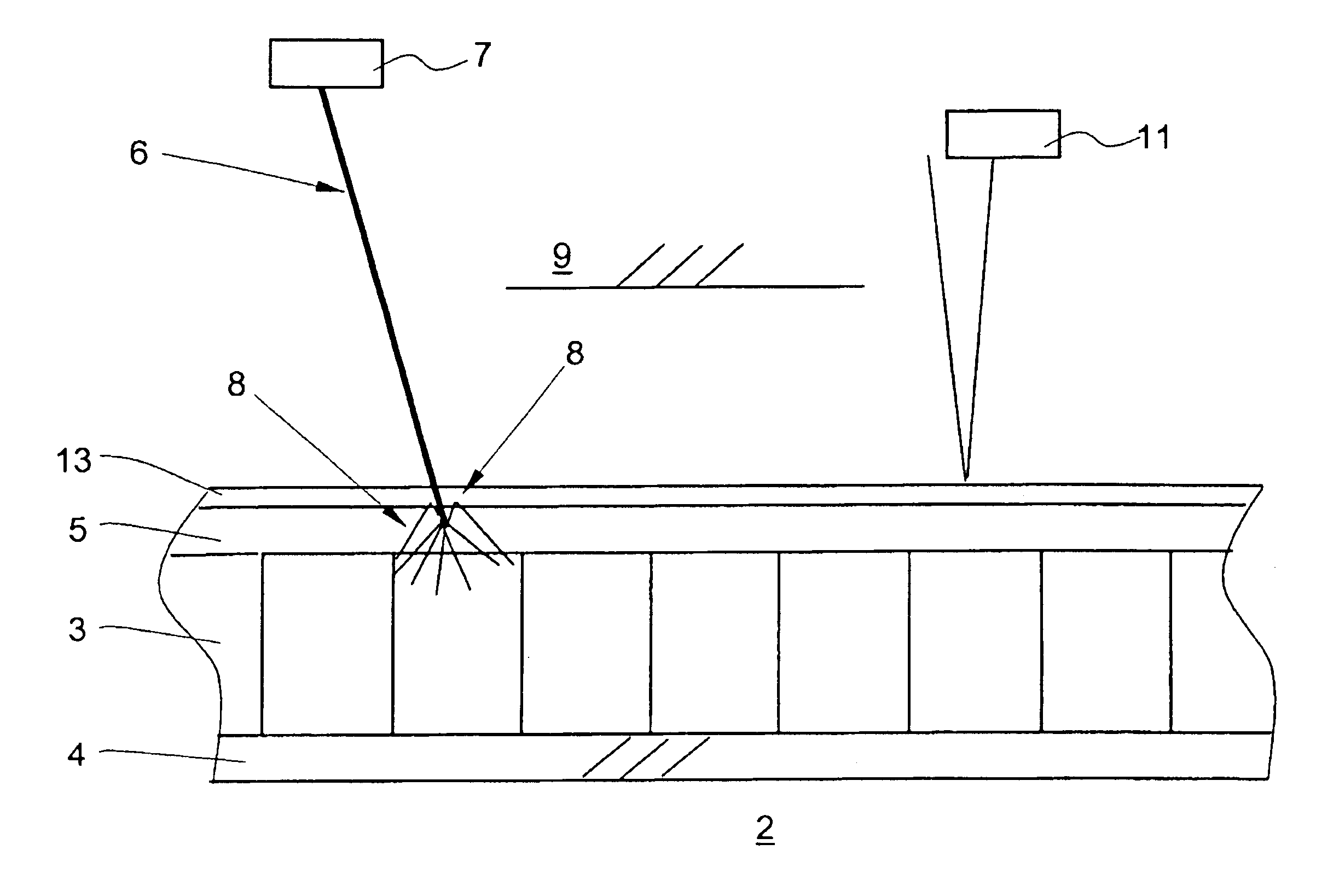
[0017]It is one aspect of embodiments of the present invention to improve the detection characteristics of the current photo-detector having a conversion layer, so that a higher yield is achieved and the presence of ghost images is suppressed.
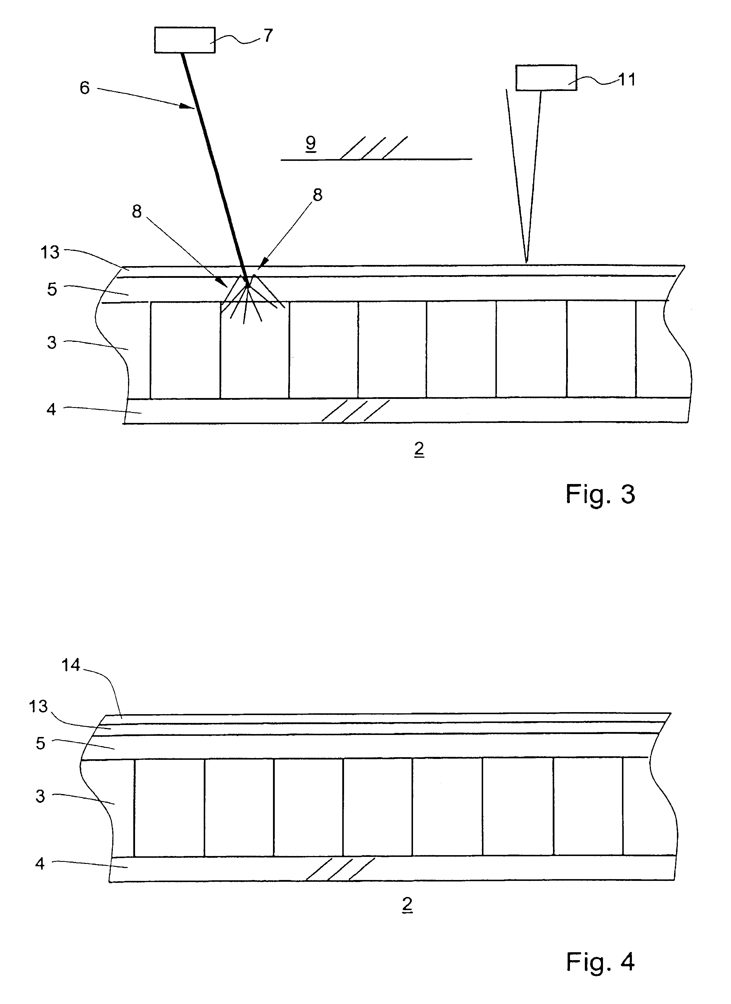
[0019]Such a filter material tends to reduce the number of visible and infrared stray light photons reaching the photodiodes, creating an effectively solar blind detector. The top layer thus enhances the spectral selectivity of the image sensor.
[0021]This will increase the detector signal with the reflected fraction of the secondary photons originally emitted away from the photosensitive surface, and thereby reduce the loss in yield. It will also reduce the contribution of the backward emitted and at some point reflected secondary radiation.

Problems solved by technology

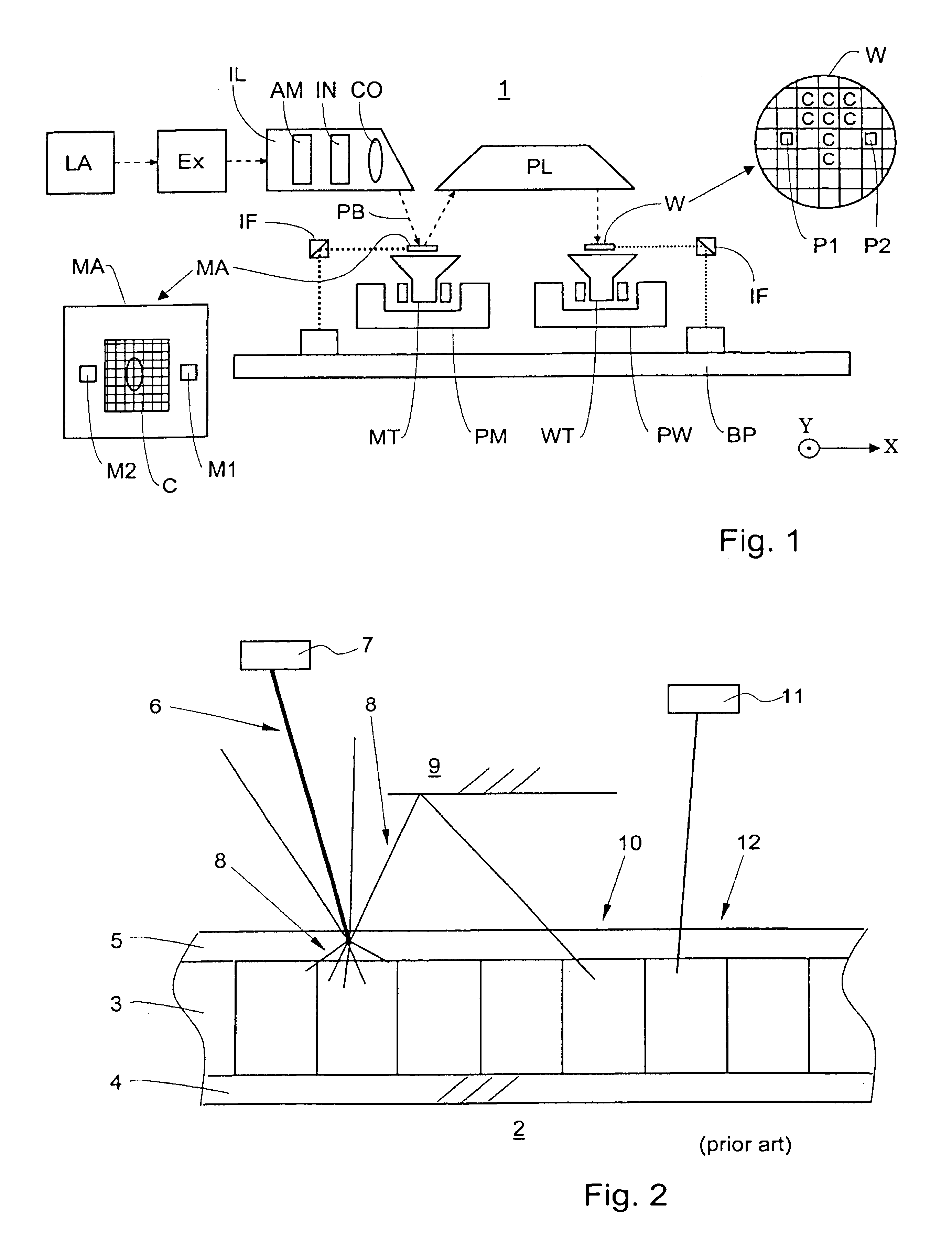
This results in a significant yield loss for the photo detector, since only half of the incident radiation energy is detected.
Especially if this photo-detector array is used as the detection part of a sensor module which consists of said photo-detector array in conjunction with an optical element with a spatially varying transmission or phase distribution, for e.g. alignment or dose measurements, in front of the array, this additional optical element will easily give rise to such spurious reflections.
This effect results in the loss of spatial resolution and in the generation of ‘unwanted’ ghost images on the image sensor.
In addition, because of the relative high sensitivity for visible and infrared radiation, stray light in these wavelength ranges gives a large unwanted background.
In a scanner, other measurement systems based on optical methods that employ radiation at these wavelengths will give rise to an unwanted cross-talk between different diagnostic systems.

Method used


Image

  • Lithographic apparatus, device manufacturing method, and device manufactured thereby
  • Lithographic apparatus, device manufacturing method, and device manufactured thereby
  • Lithographic apparatus, device manufacturing method, and device manufactured thereby

Examples


embodiment 1

[0036]FIG. 1 schematically depicts a lithographic projection apparatus 1 according to a particular embodiment of the invention. The apparatus includes:[0037]a radiation system Ex, IL, for supplying a projection beam PB of radiation (e.g. light in the deep ultraviolet region). In this particular case, the radiation system also comprises a radiation source LA;[0038]a first object table (mask table) MT provided with a mask holder supported on a base plate BP for holding a mask MA (e.g. a reticle), and connected to first positioning means PM for accurately positioning the mask with respect to item PL;[0039]a second object table (substrate table) WT provided with a substrate holder for holding a substrate W (e.g. a resist coated silicon wafer), and connected to second positioning means PW for accurately positioning the substrate with respect to item PL; and[0040]a projection system (“lens”) PL for imaging an irradiated portion of the mask MA onto a target portion C (e.g. comprising one o...


PUM


Abstract

A lithographic projection apparatus includes a radiation system for providing a projection beam of primary radiation, a support structure for supporting patterning structure, the patterning structure serving to pattern the projection beam according to a desired pattern, a substrate table for holding a substrate, a projection system for projecting the patterned beam onto a target portion of the substrate, a radiation sensor which is moveable in a path traversed by the projection beam, for receiving primary radiation out of the projection beam, the sensor including a radiation-sensitive material which converts incident primary radiation into secondary radiation, a radiation detector capable of detecting said secondary radiation emerging from said material, and a filter material for preventing secondary radiation from traveling in a direction away from the radiation detector.

Description

[0001]This application claims priority from European Patent Application 02080107.2, filed Dec. 4, 2002 which is herein incorporated by reference in its entirety.BACKGROUND OF THE INVENTION[0002]1. Field of the Invention[0003]The present invention relates generally to a lithographic projection apparatus and more particularly to a lithographic projection apparatus having a moveable radiation sensor in a path of the projection beam.[0004]2. Description of the Related Art[0005]The term “patterning device” or “patterning structure” as here employed should be broadly interpreted as referring to means that can be used to endow an incoming radiation beam with a patterned cross-section, corresponding to a pattern that is to be created in a target portion of the substrate; the term “light valve” can also be used in this context. Generally, the said pattern will correspond to a particular functional layer in a device being created in the target portion, such as an integrated circuit or other d...

Claims


Application Information

Patent Timeline
IPC IPC(8): G01J1/58G01J1/00G01J1/42G03F7/20G21K5/00G01T1/20G02B5/26G21K5/02H01L21/027
CPCG01J1/429G03F7/7085G03F7/70558G01J1/58G03F7/20
Inventor VAN DE KERHOF, MARCUS ADRIANUSDE BOEIJ, WILHELMUS PETRUSHEMERIK, MARCEL MAURICE
Owner ASML NETHERLANDS BV
Learn More