
Optical detection systems and methods of using the same

a detection system and optical technology, applied in the field of optical detection systems, can solve the problems of difficult to distinguish between multiple simultaneous events, inconvenient operation, and inability to provide modal interference-based systems with very limited information about an even

Active Publication Date: 2013-08-08
AVALON SCI
View PDF4 Cites 13 Cited by
  • Summary
  • Abstract
  • Description
  • Claims
  • Application Information

AI Technical Summary

Problems solved by technology

Each of these conventional systems suffers from certain deficiencies.
For example, modal interference-based systems provide very limited information about an event such as the location and / or time of an event.
Further, such systems have difficulty distinguishing between multiple simultaneous events.
Time-correlated Mach-Zehnder-based systems have difficulty discerning continuous events (e.g., a pipe leak).
Coherent Rayleigh backscattering-based systems suffer from high interrogator costs and limited sensitivity.
Further, certain of these conventional systems utilize photonics boxes located throughout an array that require electrical power to be provided locally, rendering such systems impractical for long distance applications such as border security.

Method used


Image

  • Optical detection systems and methods of using the same
  • Optical detection systems and methods of using the same
  • Optical detection systems and methods of using the same

Examples


Embodiment Construction

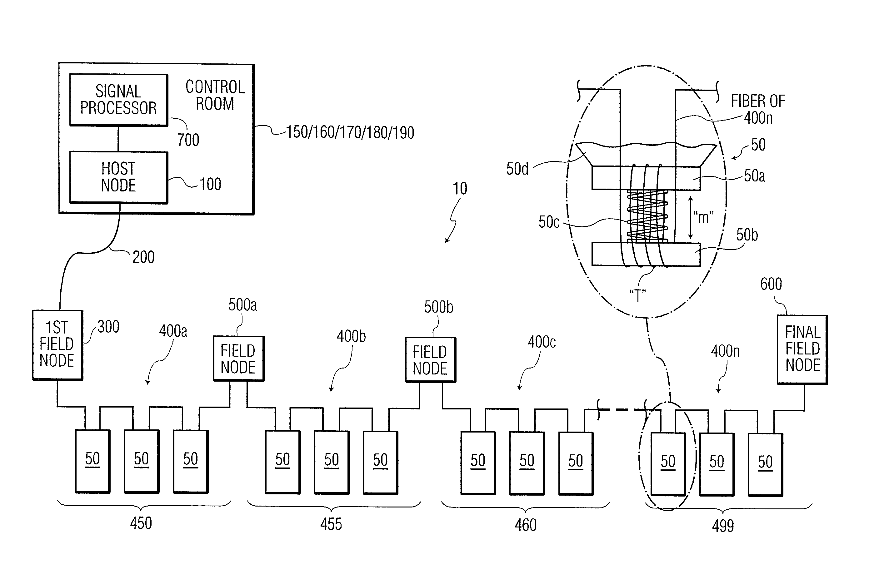
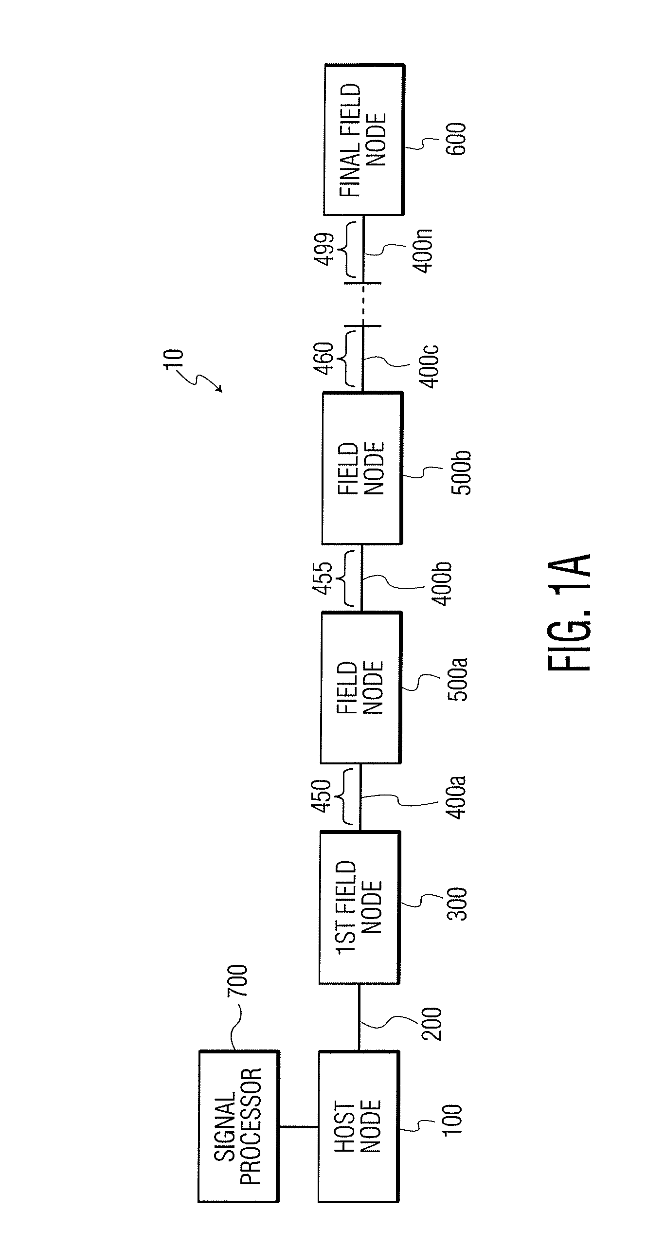
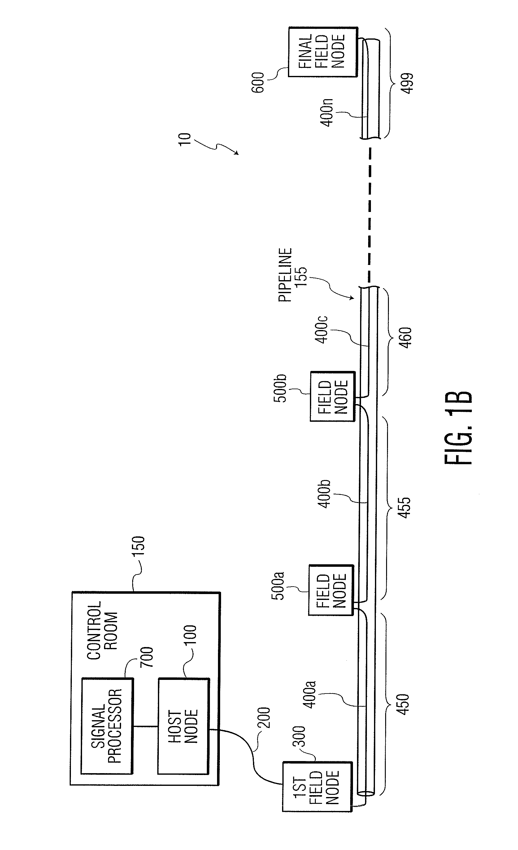
[0022]In order to enable detection and classification of events in connection with a system or location to be monitored (e.g., a pipeline, a mine, a fence line, an open area, a body of water, a perimeter, etc.), it is desirable to have a high fidelity electronic representation of a disturbance (e.g., mechanical vibration, acoustic vibration, impact, intrusion, etc.). According to certain exemplary embodiments of the present invention, an optical detection system is provided which utilizes interferometers with high linearity and dynamic range (e.g., certain linearized Sagnac interferometers). The optical detection systems may also include a low noise, low distortion, optical receiver.

[0023]In certain more specific exemplary embodiments of the present invention, optical detection systems utilizing an integrated sensor array (e.g., including a sensing cable divided into sensing zones which may be arranged to include a series of linearized Sagnac interferometers) for monitoring systems / ...


PUM


Abstract

An optical detection system. The optical detection system includes a host node having (a) an optical source for generating optical signals, and (b) an optical receiver. The optical detection system also includes a plurality of fiber optic sensors for converting at least one of vibrational and acoustical energy to optical intensity information, each of the fiber optic sensors having: (1) at least one length of optical fiber configured to sense at least one of vibrational and acoustical energy; (2) a reflector at an end of the at least one length of optical fiber; and (3) a field node for receiving optical signals from the host node, the field node transmitting optical signals along the at least one length of optical fiber, receiving optical signals back from the at least one length of optical fiber, and transmitting optical signals to the optical receiver of the host node.

Description

RELATED APPLICATIONS[0001]This application claims the benefit of priority to U.S. Provisional Patent Application Ser. No. 61 / 338,466, filed on Feb. 18, 2010, and to U.S. Provisional Patent Application Ser. No. 61 / 367,515, filed on Jul. 26, 2010, the contents of both of which are incorporated in this application by reference.TECHNICAL FIELD[0002]This invention relates generally to the field of optical detection systems and, more particularly, to improved systems and methods for accurately detecting presence in, and / or interference with, an area to be monitored using fiber optics.BACKGROUND OF THE INVENTION[0003]Fiber optic sensing systems have been used in a number of applications including perimeter security, acoustic sensing, and leak detection. Examples of conventional fiber optic sensing systems include (1) modal interference-based systems; (2) time-correlated Mach-Zehnder interferometer-based systems; and (3) coherent Rayleigh backscattering-based systems. Each of these conventi...

Claims


Application Information

Patent Timeline
Patent Type & Authority Applications(United States)
IPC IPC(8): G01V8/10G01B11/16G01V8/24
CPCG01V1/226G01V8/10G01B11/161G01V8/24G01B9/02G01D5/353G01D5/35306G01H9/004G01M3/38G08G1/04
Inventor GOLDNER, ERIC LEEBAKER, GERALD ROBERTANDERSEN, JAMES KENGOCHERBETTCHIAN, AGOP HYGASOV
Owner AVALON SCI
Learn More