Front light module

a front light and module technology, applied in the field of front light modules, can solve the problems of reducing unable to be processed easily on the light-guiding plate, and the size of each microstructure is so small, so as to achieve sufficient brightness, shorten the manufacturing process and increase the light-guiding efficiency of the light-guiding plate

Inactive Publication Date: 2013-08-08
KUO HENG SHENG
View PDF2 Cites 5 Cited by
  • Summary
  • Abstract
  • Description
  • Claims
  • Application Information

AI Technical Summary

Benefits of technology

[0010]In comparison with prior art, the light-guiding plate of the front light module of the present invention comprises the first reflecting surface facing the panel and the second reflecting surface opposite to the first reflecting surface. Further, an included angle is formed between the panel and the first reflecting surface or the second reflecting surface. The present invention can replace the conventional light-guiding plate in which the microstructures are formed on an outer end surface (equivalent to the second reflecting surface of the present invention) of the light-guiding plate to reflect the light. Thus, the present invention can shorten the manufacturing process of the light-guiding plate. Further, the first reflecting surface or the second reflecting surface of the present invention is an inclined surface for reflecting most of the light emitted by the light source onto the panel uniformly. Thus, the present invention increases the light-guiding efficiency of the light-guiding plate and provides sufficient brightness. Therefore, the practicability of the present invention is increased.

Problems solved by technology

However, the size of each microstructure is so small that they cannot be processed on the light-guiding plate easily.
As a result, the light-guiding efficiency of the light-guiding plate is reduced.

Method used


Image

  • Front light module
  • Front light module
  • Front light module

Examples


Embodiment Construction

[0023]The detailed description and technical contents of the present invention will become apparent with the following detailed description accompanied with related drawings. It is noteworthy to point out that the drawings is provided for the illustration purpose only, but not intended for limiting the scope of the present invention.

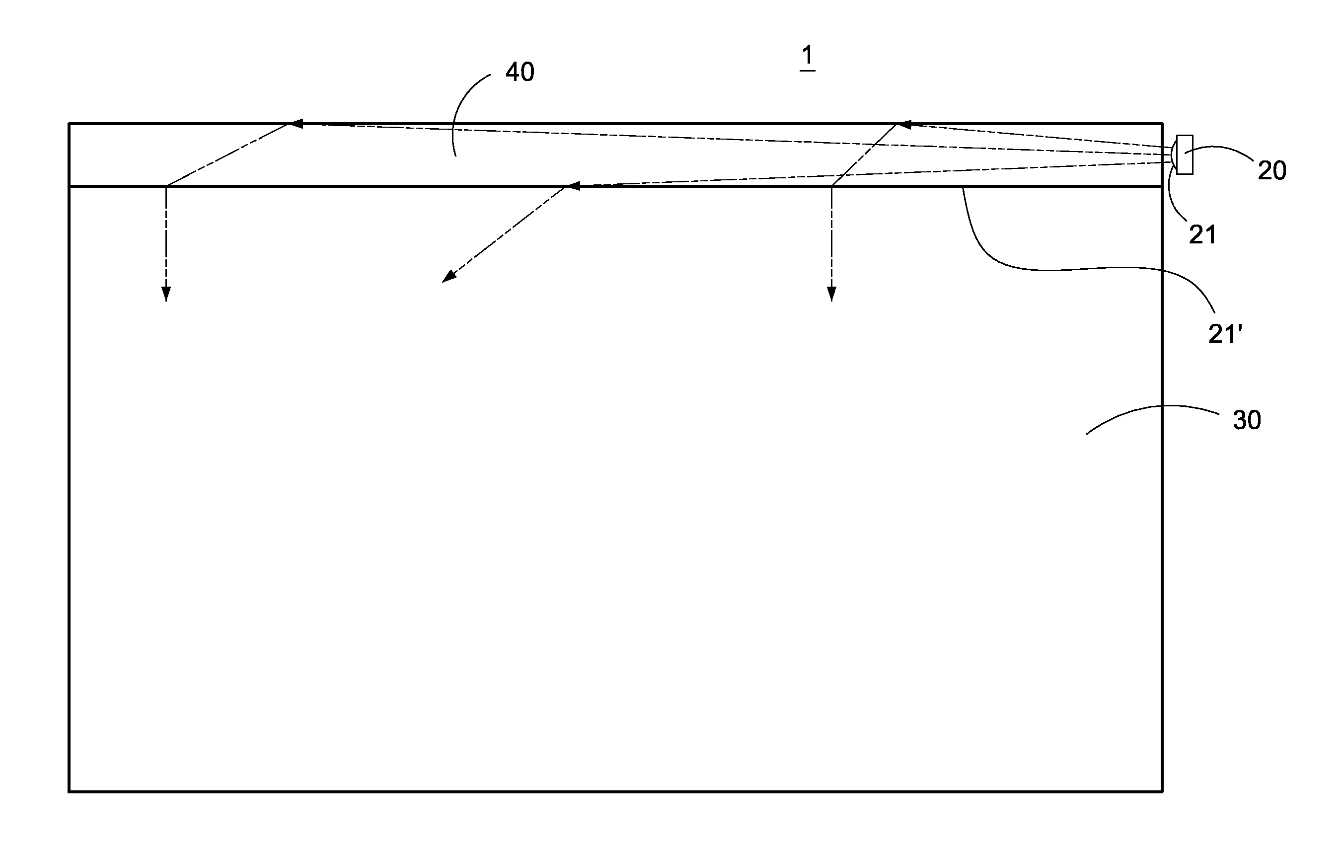
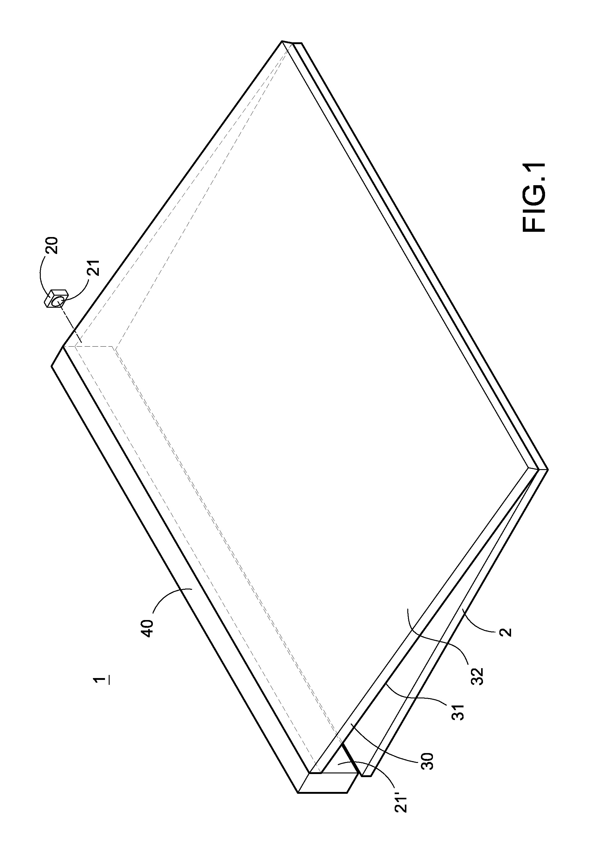
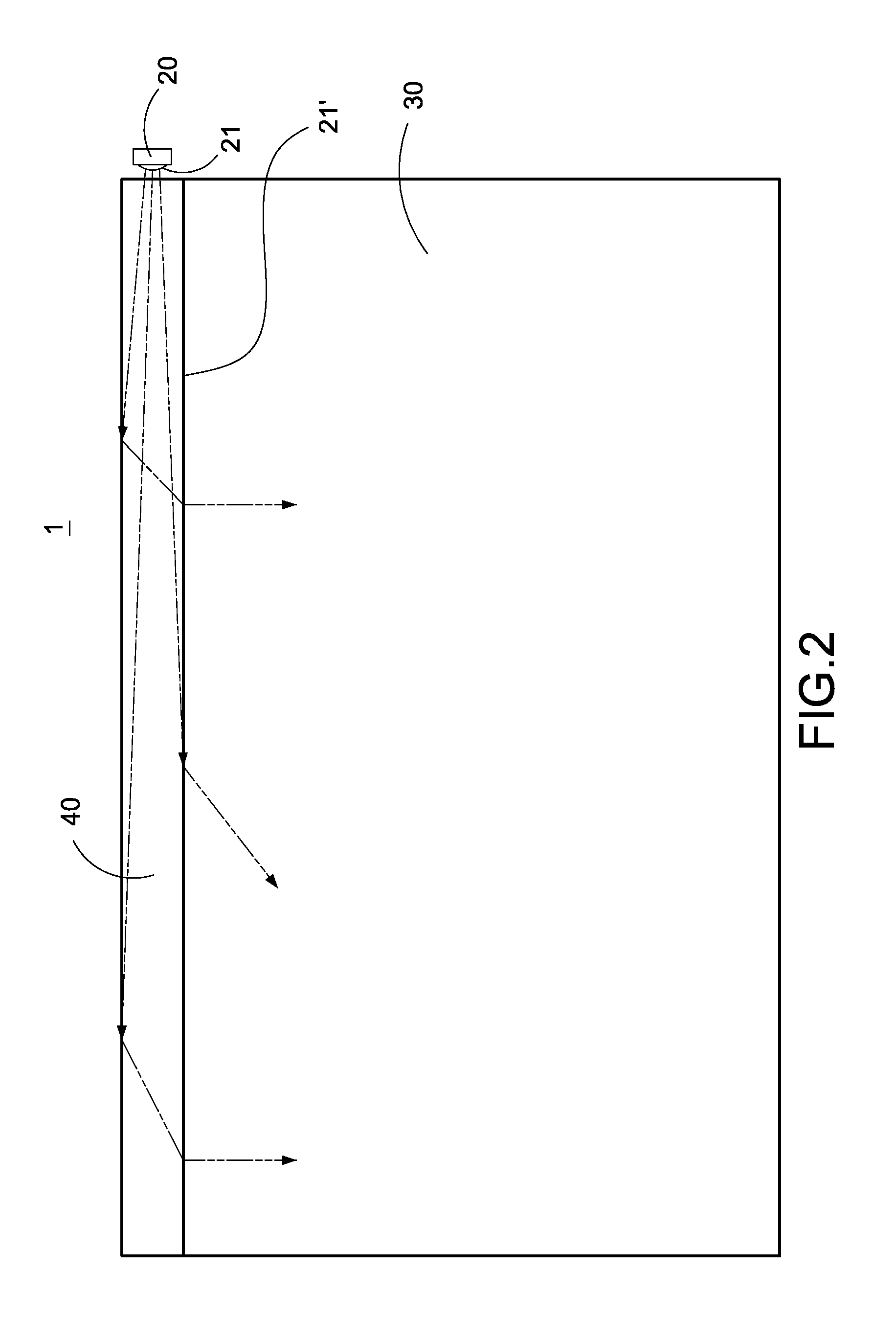
[0024]Please refer to FIGS. 1 and 2. FIG. 1 is a perspective view showing the external appearance of the front light module according to the present invention, and FIG. 2 is a top view showing the front light module of the present invention. The front light module 1 of the present invention is used to provide light to a panel 2. The front light module 1 includes a light source 20, a light-guiding plate 30, and a second light-guiding plate 40.

[0025]The light source 20 is an optical diode such as a light emitting diode (LED) or a laser diode (LD), but it is not limited thereto. The light source 20 may be a cold cathode fluorescent lamp (CCFL) or other ligh...


PUM


Abstract

A front light module includes a light source and a light-guiding plate. The light-guiding plate is disposed outside a panel. The light-guiding plate receives the light emitted by the light source and reflects the light onto the panel. The light-guiding plate includes a first reflecting surface facing the panel and a second reflecting surface opposite to the first reflecting surface. An included angle is formed between the panel and the first reflecting surface or the second reflecting surface. The front light module can reflect the light onto the panel uniformly to generate sufficient brightness.

Description

BACKGROUND OF THE INVENTION[0001]1. Field of the Invention[0002]The present invention relates to a light module, and in particular to a front light module.[0003]2. Description of Prior Art[0004]In general, a display panel is additionally provided with a light module for generating a light source of sufficient brightness and uniform distribution. By this structure, the display panel can display images with uniform and high brightness as well as a wide viewing angle.[0005]Based on the position of the light module, a front light module is a light module mounted in front of glass chips and color filters. The front light module is capable of converting a point or linear light source into a planar light source via a light-guiding structure, thereby generating a planar surface having high brightness and uniform luminance. In the daytime and in a place with sufficient illumination, the front light module can generate sufficient brightness by using an external light source. When the external...

Claims


Application Information

Patent Timeline
Patent Type & Authority Applications(United States)
IPC IPC(8): F21V7/04
CPCG02F2001/133616G02B6/0028G02B6/0055G02B6/0038G02B6/0046G02B6/0031G02F1/133616
Inventor KUO, HENG-SHENG
Owner KUO HENG SHENG
Why Eureka
Try Eureka