Force Transmission Arrangement for Auto-Injector

a technology of auto-injector and transmission arrangement, which is applied in the field of transmission arrangement, can solve the problems of user's underdose, user's inability to deliver an injection, and the injection force may be too high for the user,

Active Publication Date: 2013-08-08
SANOFI AVENTIS DEUT GMBH
View PDF1 Cites 47 Cited by
  • Summary
  • Abstract
  • Description
  • Claims
  • Application Information

AI Technical Summary

Benefits of technology

[0041]An intermediary component may be arranged for transmitting translation of the plunger to the syringe in order to first advance the syringe and needle while avoiding load onto the stopper thus avoiding wet injection, i.e. medicament leaking out of the needle's tip before the needle is fully inserted into the injection site. The intermediary component is furthermore arranged to be decoupled from the syringe when the needle has reached a predefined injection depth. At the same time the translation is coupled to the stopper in order to inject the dose.
[0042]In a preferred embodiment a shroud is arranged at least partially inside the housing. The shroud may be slidable in longitudinal direction between at least a retracted position, in which the needle is exposable and an advanced position, in which the needle is covered by the shroud. The shroud is arranged to be locked in the retracted position prior to manual operation of the activation means. Once the drive means has been released the shroud may be unlocked and automatically move towards the advanced position under load of a syringe spring. This automatic movement will happen when the auto-injector is removed from the injection site in the course of an injection or after the injection has been completed in order to hide the needle and keep the user from injuring themselves. As long as the user maintains the auto-injector pressed against the injection site during the injection cycle, the shroud will remain in the retracted position.

Problems solved by technology

Administering an injection is a process which presents a number of risks and challenges for users and healthcare professionals, both mental and physical.
There are numerous disadvantages for the user from this approach.
This means that the user can deliver an underdose if the device is not used properly (i.e. the plunger is not fully pressed to its end position).
Injection forces may be too high for the user, in particular if the patient is elderly or has dexterity problems.
The extension of the button / plunger may be too great.
Thus it can be inconvenient for the user to reach a fully extended button.
The combination of injection force and button extension can cause trembling / shaking of the hand which in turn increases discomfort as the inserted needle moves.
This may lead to variation in the delivery of the dose over the injection cycle.

Method used


Image

  • Force Transmission Arrangement for Auto-Injector
  • Force Transmission Arrangement for Auto-Injector
  • Force Transmission Arrangement for Auto-Injector

Examples


Embodiment Construction

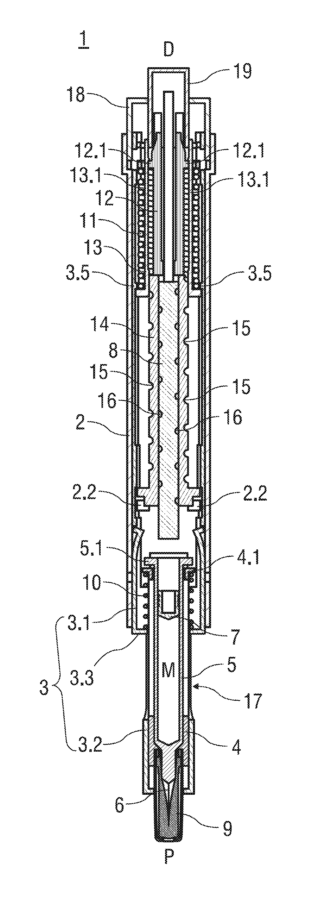
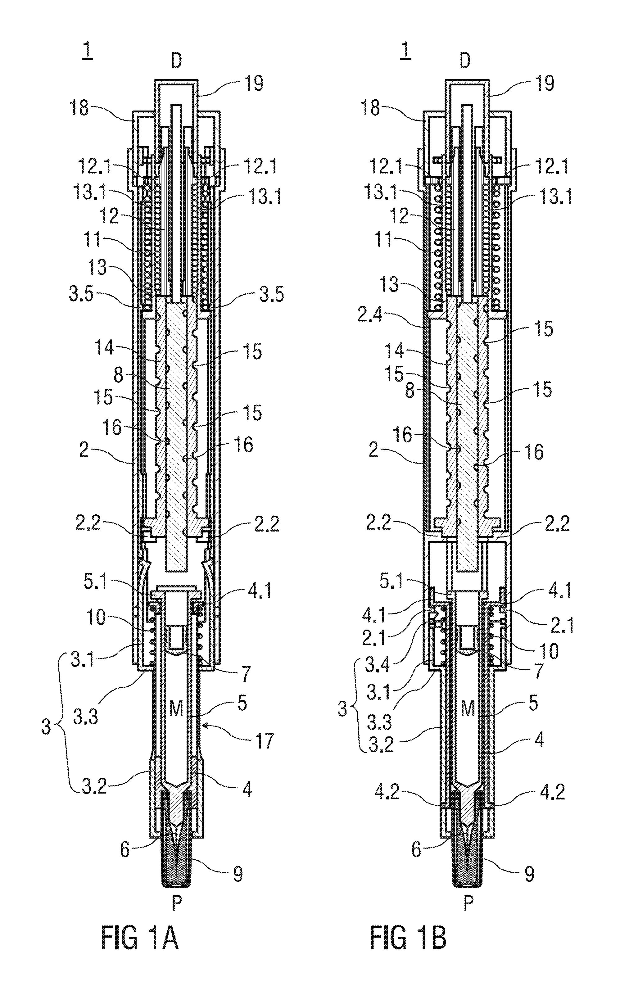
[0127]FIG. 1 shows two longitudinal sections in two section planes of an auto-injector 1 with force control in an as shipped state. The auto-injector 1 comprises an elongate housing 2, an essentially tubular shroud 3 arranged inside the housing 2 and slidable in longitudinal direction with respect to the housing 2. A distal portion 3.1 of the shroud has an external diameter selected to fit into the housing 2. The distal portion 3.1 extends essentially through the entire housing 2 to the distal end D. The biggest part of the distal portion 3.1 consists of two longitudinal extensions rather than a tube shape in order to allow other parts of the auto-injector 1 to engage in the housing 2 for preventing relative rotation. This could alternatively be achieved by a tubular distal portion 3.1 with longitudinal slots. A proximal portion 3.2 of the shroud 3 has a reduced diameter compared to the distal portion 3.1 for slidably accommodating a syringe carrier 4. The syringe carrier 4 holds a ...


PUM


Abstract

The invention relates to a transmission arrangement for controlling a force of a translation, the transmission arrangement comprising a drive collar (13) connectable to a translative drive means (11) and prevented from rotating with respect to a ground (12) of the drive means (11), a flange face of the drive collar (13) bearing against a mating flange face of a friction collar (20), the friction collar (20) slidable in longitudinal direction and rotationally constrained by engagement in a cam track (12.3), another flange face of the friction collar (20) bearing against a mating flange face of a plunger (8), the plunger (8) slidable in longitudinal direction and prevented from rotating.

Description

TECHNICAL FIELD [0001]The invention relates to a transmission arrangement for controlling a force of a translation, in particular for application in an auto-injector for delivering a dose of a liquid medicament.BACKGROUND OF THE INVENTION[0002]Administering an injection is a process which presents a number of risks and challenges for users and healthcare professionals, both mental and physical.[0003]Injection devices (i.e. devices capable of delivering medicaments from a medication container) typically fall into two categories—manual devices and auto-injectors.[0004]In a manual device—the user must provide the mechanical energy to drive the fluid through the needle. This is typically done by some form of button / plunger that has to be continuously pressed by the user during the injection. There are numerous disadvantages for the user from this approach. If the user stops pressing the button / plunger, then the injection will also stop. This means that the user can deliver an underdose ...

Claims


Application Information

Patent Timeline
Patent Type & Authority Applications(United States)
IPC IPC(8): A61M5/315A61M5/20
CPCA61M5/2033A61M5/3158A61M5/3202A61M5/326A61M5/46A61M5/482A61M5/484A61M2005/206A61M2005/208A61M2005/2086A61M2005/2418A61M2005/3103A61M2005/3152A61M2005/3247A61M2205/581A61M2205/583A61M5/20A61M5/315
Inventor EKMAN, MATTHEWBARROW-WILLIAMS, TIMOTHY DONALDKEMP, THOMAS MARK
Owner SANOFI AVENTIS DEUT GMBH
Why Eureka
Try Eureka