Apparatus and system for turning and positioning a patient

a patient and apparatus technology, applied in the field of apparatus, system and method for turning and positioning a patient, can solve the problems of inability to move patients, inability to move, and inability to move, and achieve the effect of reducing the friction of the sliding member

Active Publication Date: 2013-08-15
SAGE PRODS
View PDF6 Cites 50 Cited by
  • Summary
  • Abstract
  • Description
  • Claims
  • Application Information

AI Technical Summary

Benefits of technology

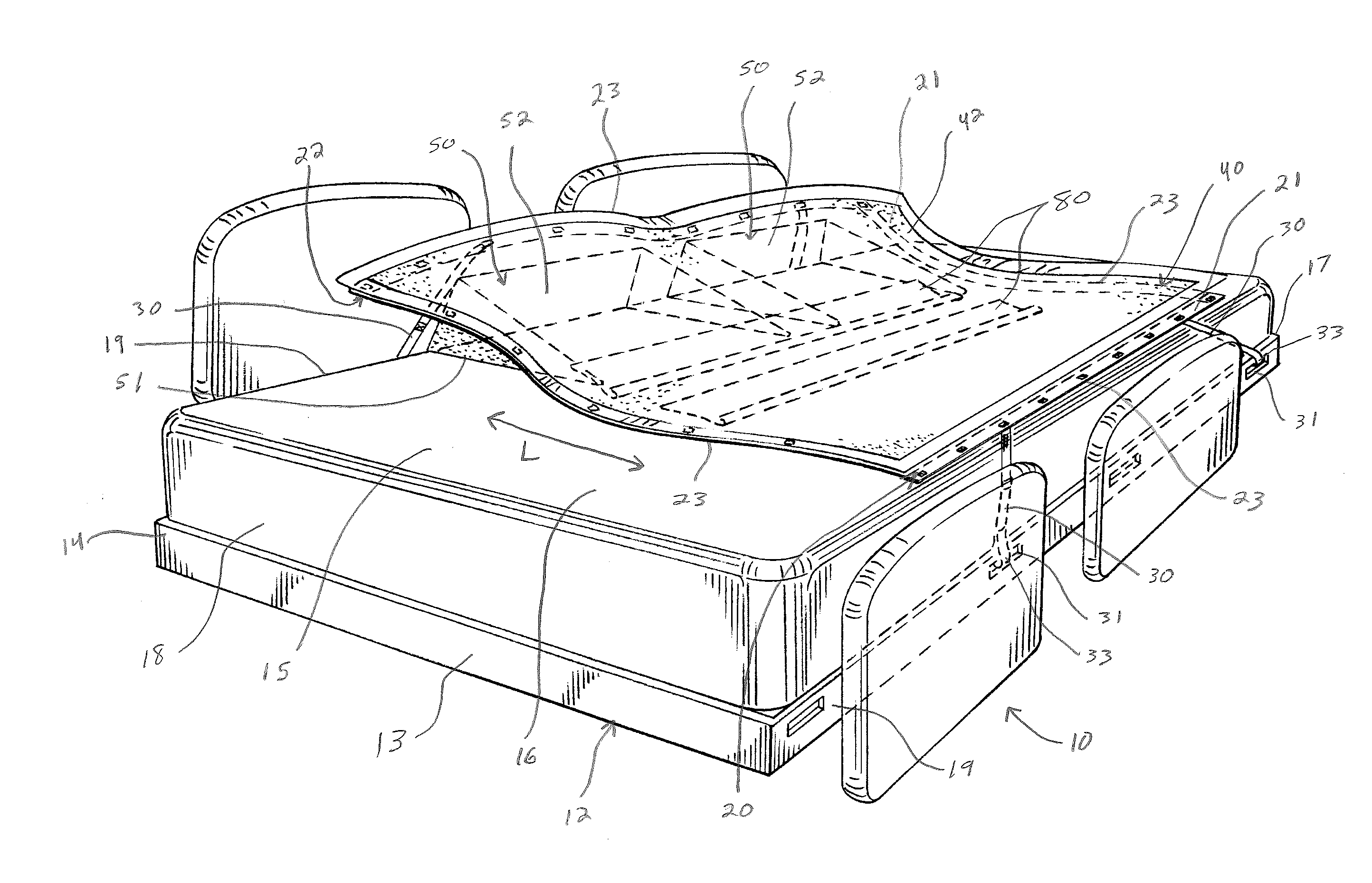
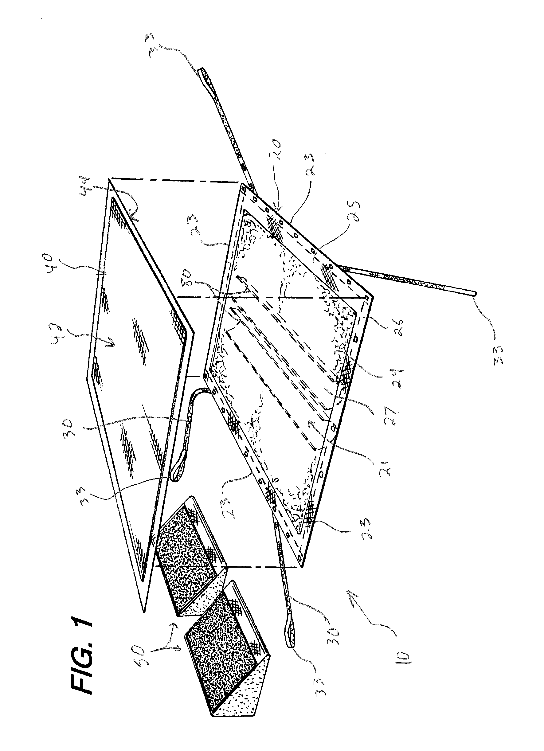
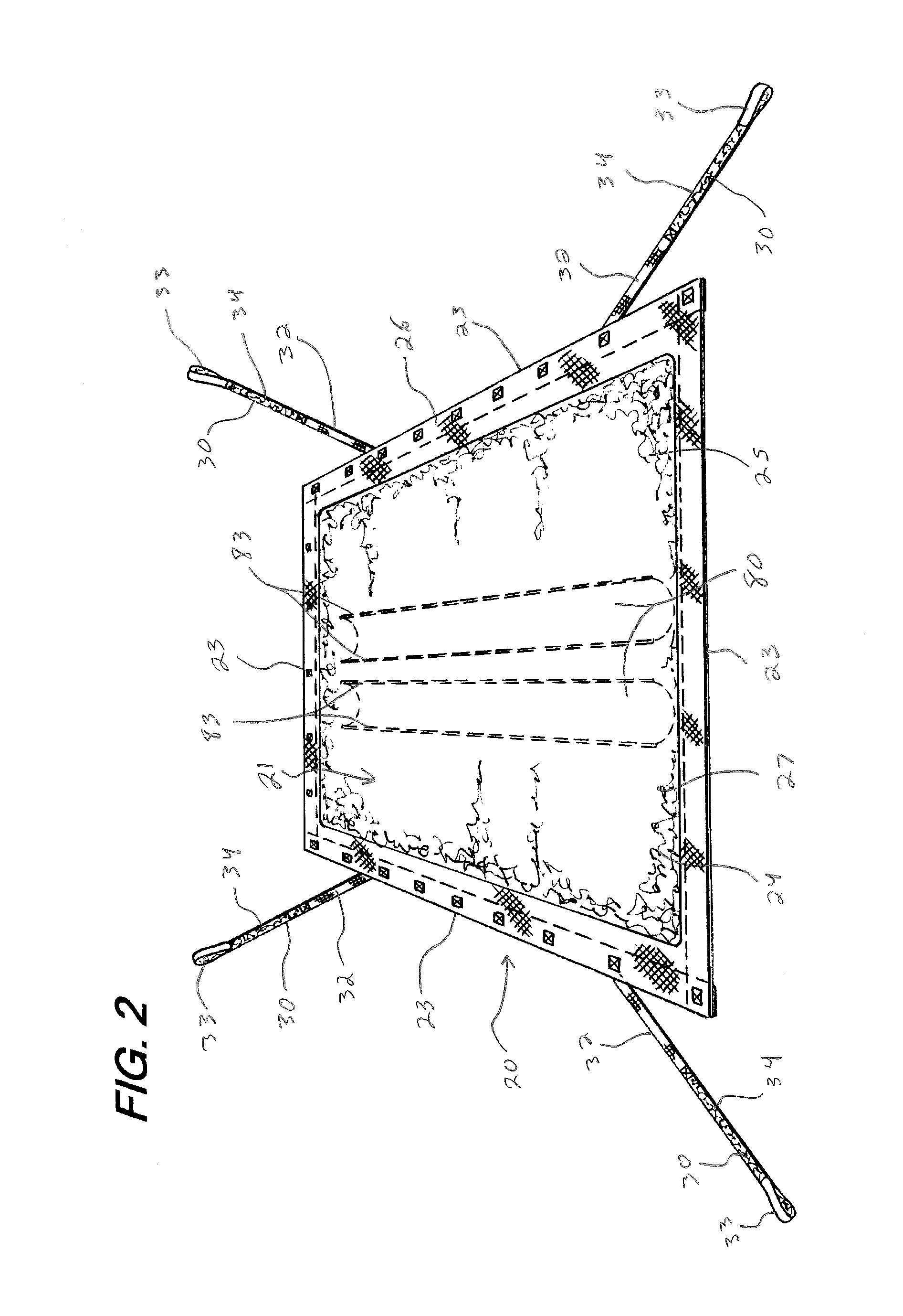
[0012]Additional aspects of the invention relate to a device or system for use with a bed having a frame and a supporting surface supported by the frame. The system includes a sheet having a bottom surface adapted to be placed above the supporting surface of the bed and a top surface opposite the bottom surface, and a sliding member formed of a low friction material and connected to the bottom surface of the sheet. The bottom surface of the sheet has a low friction surface forming at least a portion of the bottom surface, and the top surface has a high friction surface forming at least a portion of the top surface, such that the top surface provides greater slipping resistance than the bottom surface. The sheet further has a top edge configured to be positioned proximate a head of the bed, a bottom edge configured to be positioned proximate a foot of the bed, and opposed side edges located between the top and bottom edges. The sliding member has a fixed portion that is fixed to the bottom surface of the sheet and a free portion that is moveable over a range of movement with respect to the bottom surface of the sheet along a lateral direction extending between the side edges. At least a portion of the bottom surface of the sheet is configured to slide against the sliding member within the range of movement of the sliding member when the sheet is moved along the lateral direction, to facilitate lateral movement of the sheet.
[0020]According to a further aspect, the method may utilize a sliding member formed of a low friction material and connected to the bottom surface of the sheet, with the sliding member having a fixed portion that is fixed to the bottom surface of the sheet and a free portion that is moveable over a range of movement with respect to the bottom surface of the sheet along a lateral direction extending between side edges of the sheet. When the sheet is moved toward the back wall of the wedge, at least a portion of the bottom surface of the sheet slides against the sliding member within the range of movement of the sliding member to reduce the friction of the sliding member.

Problems solved by technology

These immobile patients are at risk for forming pressure ulcers (bed sores).
Pressure on a patient's skin, particularly for extended periods of time and in areas where bone or cartilage protrudes close to the surface of the skin, can cause pressure ulcers.
Frictional forces and shearing forces from the patient's skin rubbing or pulling against a resting surface can also cause pressure ulcers.
Excessive heat and moisture can cause the skin to be more fragile and increase the risk for pressure ulcers.
One area in which pressure ulcers frequently form is on the sacrum, because a patient lying on his / her back puts constant pressure on the sacrum, and sliding of the patient in a bed can also cause friction and shearing at the sacrum.
Additionally, some patients need to rest with their heads inclined for pulmonary reasons, which can cause patients to slip downward in the bed and cause further friction or shearing at the sacrum and other areas.
Existing devices and methods often do not adequately protect against pressure ulcers in bedridden patients, particularly pressure ulcers in the sacral region.
However, turning patients is difficult and time consuming, typically requiring two or more caregivers, and can result in injury to caregivers from pushing and pulling the patient's weight during such turning.
As a result, ensuring compliance with turning protocols, Q2 or otherwise, is often difficult.
Additionally, the pillows used in turning and supporting the patient are non-uniform and can pose difficulties in achieving consistent turning angles, as well as occasionally slipping out from underneath the patient.

Method used


Image

  • Apparatus and system for turning and positioning a patient
  • Apparatus and system for turning and positioning a patient
  • Apparatus and system for turning and positioning a patient

Examples


example

[0049]A 20″×20″ section of bed linen (60% cotton, 40% polyester, 200 threads / inch) was taped without slack to a table top. A 10″×10″ section of blue ripstop nylon was placed on top of the section of bed linen, then a 5 lb., 8″ diameter weight was centered on top of the ripstop nylon. A force gauge (Extech 475044, 44 lb. max, digital) was attached to the ripstop nylon and was used to pull / slide the weighted ripstop nylon across the surface of the bed linen. The peak force to slide was recorded. Similarly, a 20″×20″ section of tricot (warp knit tricot material that was brushed, napped, and / or sanded and treated with a hot melt adhesive) was taped without slack to a table top. A 10″×10″ section of an absorbent body pad was placed on top of the section of the tricot material (patient side facing up), then the 5 lb., 8″ diameter weight was centered on top of the body pad. The force gauge was attached to the body pad and was used to pull / slide the weighted body pad across the surface of t...


PUM


Abstract

A system for use with a bed having a frame and a supporting surface includes a sheet having a bottom surface placed above the supporting surface of the bed, a top surface, and a plurality of tether straps connected to and extending from the sheet. Each tether strap is configured for connection to the bed. The bottom surface is at least partially formed of a low friction material, and the top surface is at least partially formed of a high friction material, such that the top surface provides greater slipping resistance than the bottom surface. The tether straps include at least two pairs of tether straps, with one pair connected proximate a top edge of the sheet and another pair connected proximate a bottom edge of the sheet. The sheet may further include a sliding member on the bottom surface to assist in lateral sliding of the sheet.

Description

CROSS-REFERENCE TO RELATED APPLICATIONS[0001]The present application claims priority to and is a continuation-in-part of U.S. patent application Ser. No. 13 / 014,497 and U.S. patent application Ser. No. 13 / 014,500, both filed Jan. 6, 2011, both of which applications are incorporated by reference herein in their entireties.TECHNICAL FIELD[0002]The present invention generally relates to an apparatus, system, and method for turning and positioning a person supine on a bed or the like, and, more particularly, to a sheet having a gripping surface, a slipping surface, an absorbent pad, and / or a wedge for use in turning and positioning a supine person, as well as systems and methods including one or more of such apparatuses.BACKGROUND[0003]Nurses and other caregivers at hospitals, assisted living facilities, and other locations often care for bedridden patients that have limited or no mobility, many of whom are critically ill or injured. These immobile patients are at risk for forming press...

Claims


Application Information

Patent Timeline
Patent Type & Authority Applications(United States)
IPC IPC(8): A61G7/10
CPCA61G7/10A61G7/001A61G7/015A61G2007/0509A61G7/0525A61G7/1026A61G2007/0514A61G7/0507A61G7/0509A61G7/0514A61G7/1023
Inventor PONSI, LARRYLAYER, JAMES
Owner SAGE PRODS
Why Eureka
Try Eureka