Hydrostatic Transmission

a transmission and hydrostatic technology, applied in the direction of fluid couplings, couplings, mechanical devices, etc., can solve the problems of fluid leakage, high cost of making such main fluid passages, and high cost of making such main fluid passages, and achieve the effect of high output power of an apparatus using

Inactive Publication Date: 2013-08-15
KANZAKI KOKYUKOKI MFG
View PDF7 Cites 7 Cited by
  • Summary
  • Abstract
  • Description
  • Claims
  • Application Information

AI Technical Summary

Benefits of technology

[0008]An object of the invention is to provide an HST that can hold a sufficient hydraulic pressure in its main fluid passages against fluid leak from the main fluid passages so as to ensure a high output power of an apparatus using the HST even if the apparatus using the HST is an HMT.
[0009]To achieve the object, an HST according to the invention comprises a hydraulic pump, a hydraulic motor, first and second main fluid passages fluidly connecting the hydraulic pump to the hydraulic motor so as to constitute a closed fluid circuit, a charge fluid passage, a plurality of first charge check valves and a plurality of second charge check valves. The plurality of first charge check valves are interposed between the charge fluid passage and the first main fluid passage so as to allow fluid to flow from the charge fluid passage to the first main fluid passage when the first main fluid passage is hydraulically depressed relative to the charge fluid passage. The plurality of second charge check valves are interposed between the charge fluid passage and the second main fluid passage so as to allow fluid to flow from the charge fluid passage to the second main fluid passage when the second main fluid passage is hydraulically depressed relative to the charge fluid passage. Therefore, the increase of number of charge check valves increases the total sectional area of fluid passages between the respective first and second charge check valves and the respective first and second main fluid passages, thereby increasing flow of fluid charged into the first and second main fluid passages. Therefore, the HST can properly act even if it is subjected to a great hydraulic pressure in such a case where it is used in an HMT, for example.
[0010]In a first aspect of the HST, the HST further comprises a center section onto which the hydraulic pump and the hydraulic motor are mounted. The center section is formed therein with respective holes serving as the first and second main fluid passages and the charge fluid passage. The plurality of first charge check valves include at least one first charge check valve provided in the center section so as to be interposed between the hole serving as the charge fluid passage and the hole serving as the first main fluid passage. The plurality of second charge check valves include at least one second charge check valve provided in the center section so as to be interposed between the hole serving as the charge fluid passage and the hole serving as the second main fluid passage. Therefore, the number of charge check valves disposed outside of the center section is reduced so as to ensure the compactness of the HST.

Problems solved by technology

However, the main fluid passages of the HST are liable to leak fluid because they are subjected to high fluid pressures to ensure the high output power of the HMT.
To avoid the fluid leak, the main fluid passages must have a high quality in fluidal tightness and in strength so as to withstand the high pressure of fluid, however, it is expensive to make such main fluid passages.
However, the charge pump has a problem that when a vehicle is parked on a slope while stopping an engine, fluid leaks from the main fluid passages rapidly and the pressure of fluid in the main fluid passages becomes insufficient to hold the stationary vehicle so that the parked vehicle may unexpectedly descend the slope because the charge pump cannot be driven by the engine to compensate for the lack of pressure of fluid in the main fluid passages.
However, the fluid supply by use of the orifice is still insufficient to ensure the high output power of the HMT.
As a result, the HST of the HMT may have a problem caused by the lack of hydraulic pressure in the main fluid passages, e.g., cavitation that damages related devices and causes noise.

Method used


Image

  • Hydrostatic Transmission
  • Hydrostatic Transmission
  • Hydrostatic Transmission

Examples


Embodiment Construction

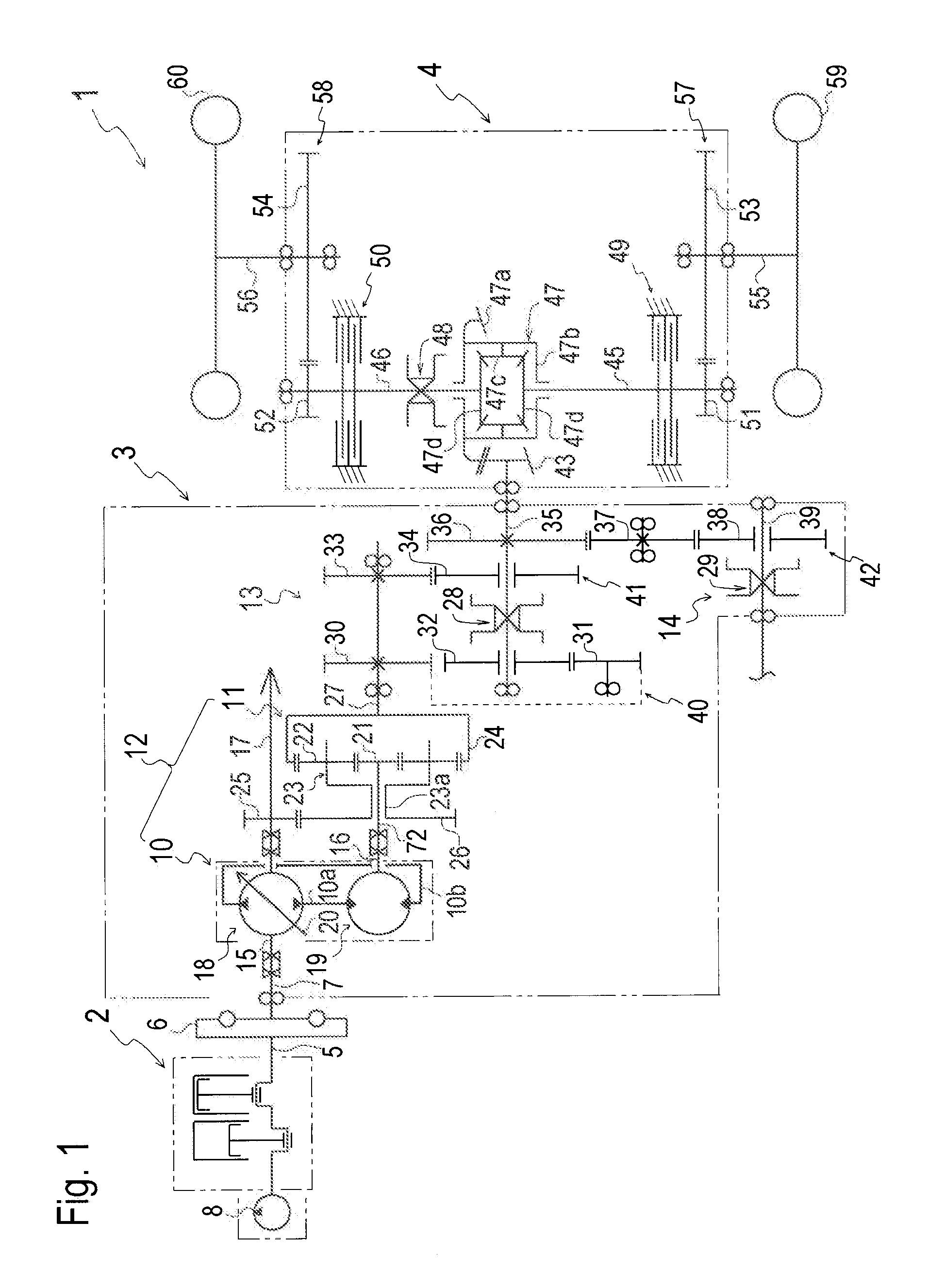
[0032]Referring to FIG. 1, a vehicle 1 is equipped with an engine 2, a transmission casing 3, a transaxle casing 4, and drive wheels 59 and 60 supported by transaxle casing 4. In this embodiment, drive wheels 59 and 60 serve as left and right rear wheels of vehicle 1, transaxle casing 4 serves as a rear transaxle casing supporting rear drive wheels 59 and 60, and vehicle 1 is equipped with an unshown front transaxle casing supporting unshown front wheels.

[0033]Engine 2 has an output shaft 5. An input shaft 7 projects outward from transmission casing 3. Input shaft 7 is drivingly connected to output shaft 5 via a rotary damper 6 for reducing vibration of output shaft 5 before the torque of output shaft 5 is transmitted to input shaft 7. A crankshaft of engine 2 serving as output shaft 5 projects outward from engine 2 so as to drive a charge pump 8 for supplying fluid to an HST 10 in transmission casing 3.

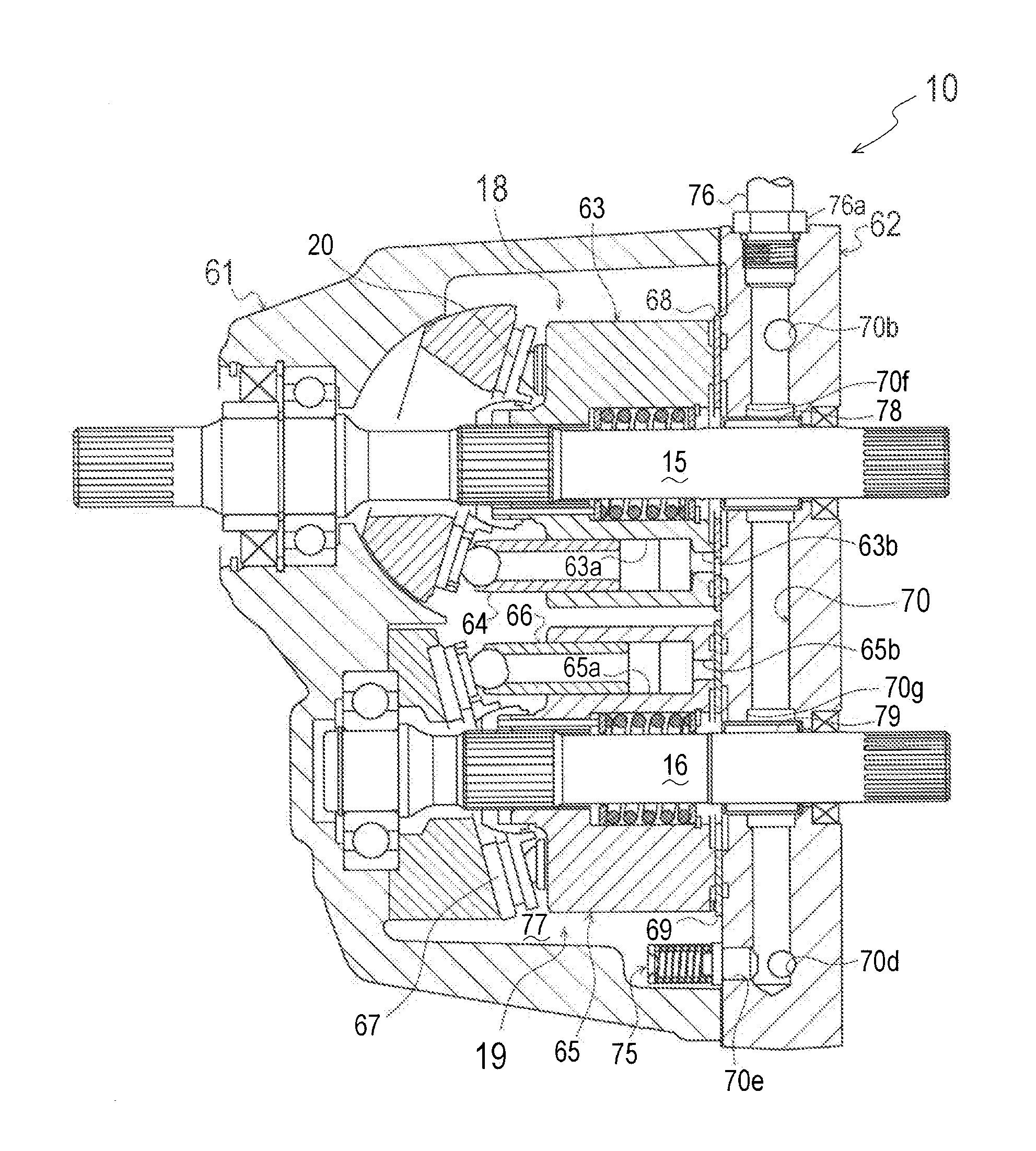
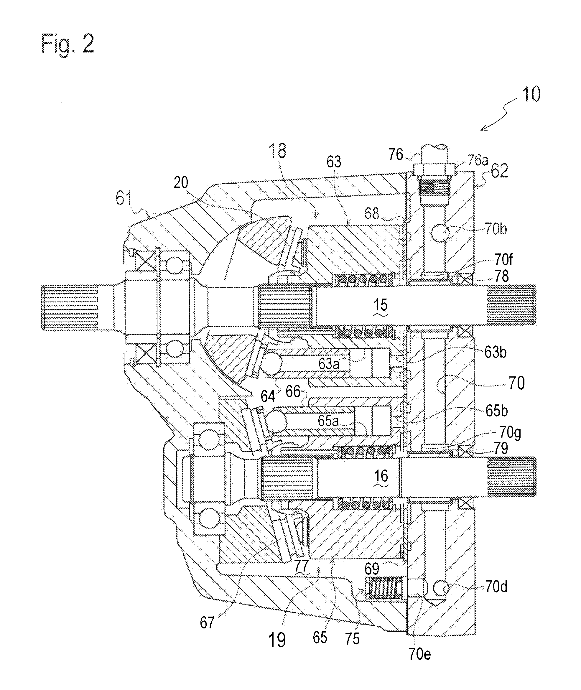
[0034]In transmission casing 3, HST 10 has a pump shaft 15 drivingly connected c...


PUM


Abstract

A hydrostatic transmission comprises a hydraulic pump, a hydraulic motor, first and second main fluid passages fluidly connecting the hydraulic pump to the hydraulic motor so as to constitute a closed fluid circuit, a charge fluid passage, a plurality of first charge check valves and a plurality of second charge check valves. The plurality of first charge cheek valves are interposed between the charge fluid passage and the first main fluid passage so as to allow only flow of fluid from the charge fluid passage to the first main fluid passage when the first main fluid passage is hydraulically depressed relative to the charge fluid passage. The plurality of second charge check valves are interposed between the charge fluid passage and the second main fluid passage so as to allow only flow of fluid from the charge fluid passage to the second main fluid passage when the second main fluid passage is hydraulically depressed relative to the charge fluid passage.

Description

BACKGROUND OF THE INVENTION[0001]1. Field of the Invention[0002]The present invention relates to a hydrostatic transmission (hereinafter, referred to as “HST”) including a hydraulic pump, a hydraulic motor, a pair of main fluid passages interposed between the hydraulic pump and the hydraulic motor so as to constitute a closed fluid circuit, and charge check valves for supplying fluid to the main fluid passages of the closed fluid circuit.[0003]2. Related Art[0004]There is a well-known conventional transmission system referred to as a “hydraulic mechanical transmission (hereinafter, referred to as “HMT”)” that is a combination of an HST and a planetary gear mechanism. The HMT is used to output high power for driving a large vehicle, e.g., a tractor, a wheel loader and a truck. However, the main fluid passages of the HST are liable to leak fluid because they are subjected to high fluid pressures to ensure the high output power of the HMT. To avoid the fluid leak, the main fluid passag...

Claims


Application Information

Patent Timeline
Patent Type & Authority Applications(United States)
IPC IPC(8): F15B21/00
CPCF15B21/00F16H61/4139F16H61/4078
Inventor MOCHIZUKI, YASUHISA
Owner KANZAKI KOKYUKOKI MFG
Why Eureka
Try Eureka