
Laser ignition apparatus

a laser ignition and apparatus technology, applied in the direction of spark plugs, basic electric elements, combustion engines, etc., can solve the problems of lowering the power density of laser light at the focal point of the combustion chamber, damage to the focusing lens or the protective cover, and the ar (anti-reflective) coating formed on the surface of the focusing lens to be peeled off, so as to achieve high reliability of the laser ignition apparatus

Active Publication Date: 2013-08-15
NIPPON SOKEN +1
View PDF7 Cites 23 Cited by
  • Summary
  • Abstract
  • Description
  • Claims
  • Application Information

AI Technical Summary

Benefits of technology

The patent describes a laser ignition apparatus for combustion engines. The apparatus includes an optical window member with a catoptric-light focal point positioned in a region where no solid material exists. The density of air is lower than that of a solid material, which prevents plasma from being generated and avoids damage to the optical elements. The optical window member can also be cleaned using a pulsed laser light to maintain high power density and secure ignition of the air-fuel mixture in the combustion chamber. The apparatus is reliable and has a high ignition efficiency.

Problems solved by technology

Consequently, damage may be made to the focusing lens or the protective cover, such as causing cracks to occur in the focusing lens or the protective cover or causing an AR (Anti-Reflective) coating formed on the surface of the focusing lens to be peeled off.
Furthermore, due to the damage made to the focusing lens or the protective cover, scattering of the laser light may occur when it passes through the damaged part of the focusing lens or the protective cover, thereby lowering the power density of the laser light at the focal point in the combustion chamber.
Consequently, it may become difficult for the laser ignition apparatus to reliably ignite the air-fuel mixture in the combustion chamber.
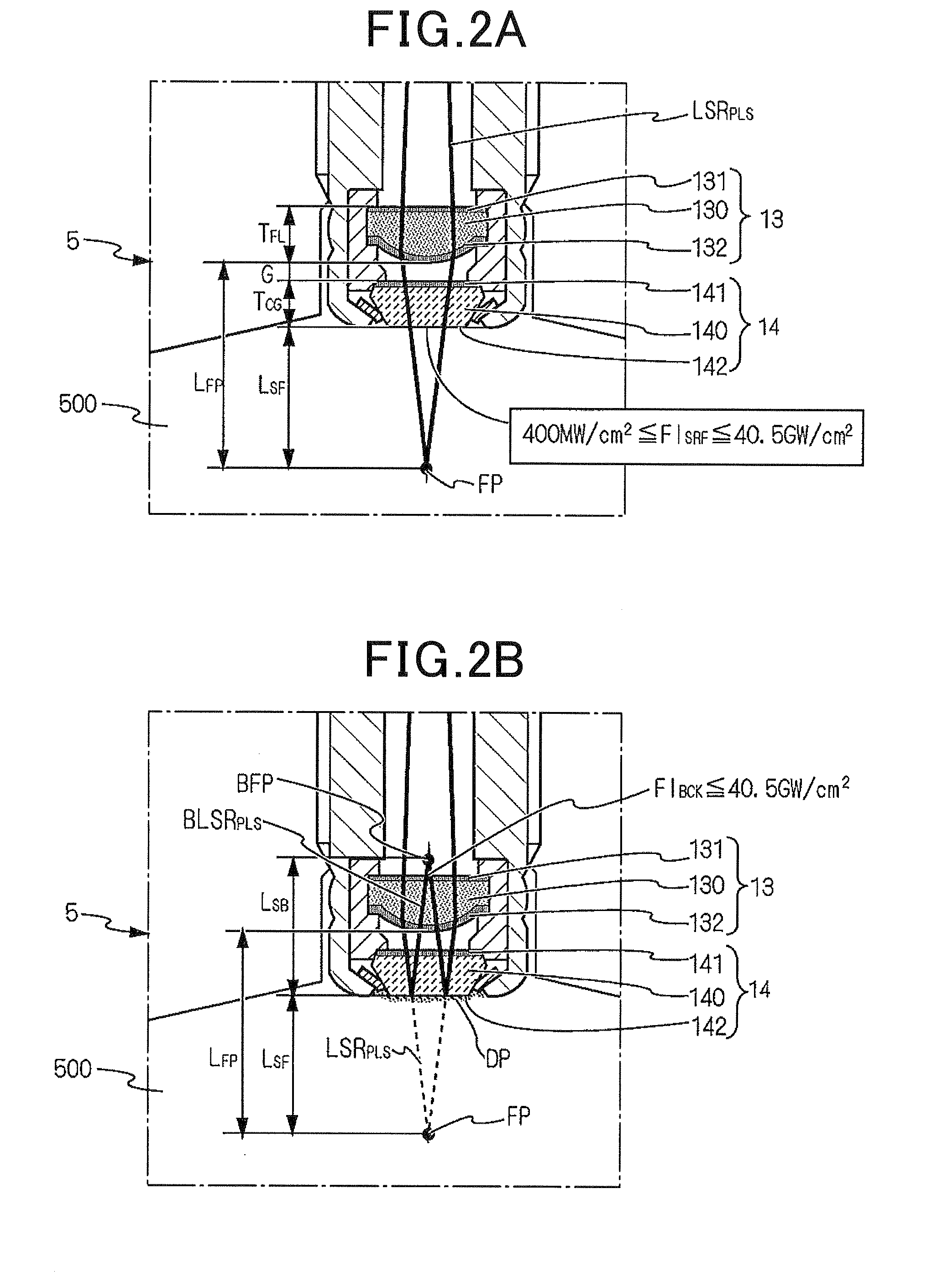
Here, the damage threshold power density is defined such that the focusing optical element can be damaged if the power density of the pulsed laser light or the catoptric light is higher than it when the pulsed laser light or the catoptric light passes through the focusing optical element.
Here, the damage threshold power density is defined such that the optical window member can be damaged if the power density of the pulsed laser light or the catoptric light is higher than it when the pulsed laser light or the catoptric light passes through the optical window member.

Method used


Image

  • Laser ignition apparatus
  • Laser ignition apparatus
  • Laser ignition apparatus

Examples


Embodiment Construction

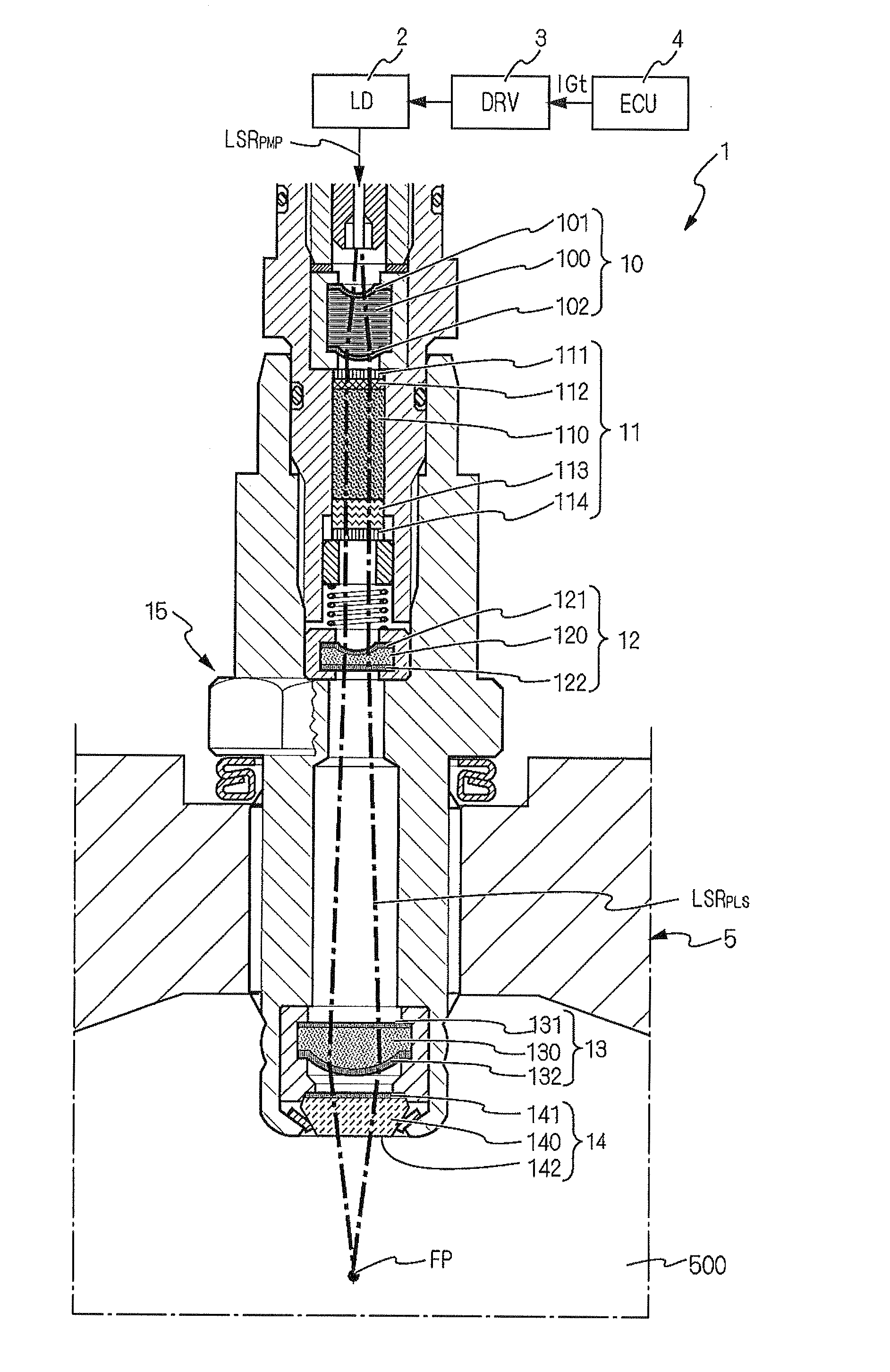
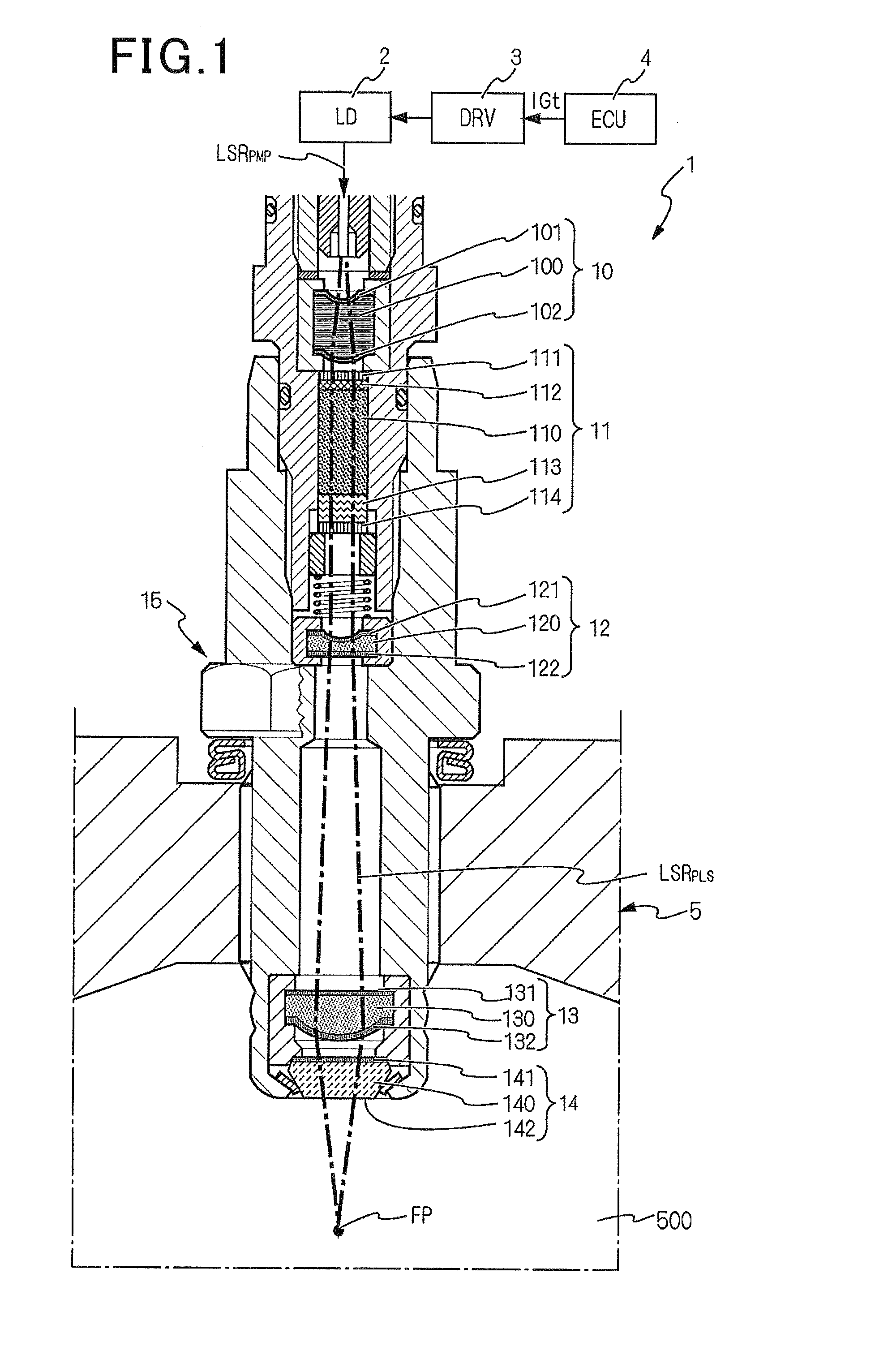
[0042]FIG. 1 shows the overall configuration of a laser ignition apparatus 1 according to an embodiment.

[0043]The laser ignition apparatus 1 is designed to ignite the air-fuel mixture in a combustion chamber 500 of an internal combustion engine 5. More particularly, the laser ignition apparatus 1 is designed to have a high capability of igniting the air-fuel mixture even when the engine 5 is a highly-charged engine, a high-compression engine or a natural gas engine that has a large bore diameter of cylinders.

[0044]As shown in FIG. 1, the laser ignition apparatus 1 is configured with an Engine Control Unit (ECU) 4, a drive unit (abbreviated to DRV in FIG. 1) 3, an excitation light source (abbreviated to LD in FIG. 1) 2, a regulating optical element 10, a laser resonator (or optical resonator) 11, an enlarging optical element 12, a focusing optical element 13, an optical window member 14 and a housing 15.

[0045]The ECU 4 is configured to output an ignition signal IGt to the drive unit ...


PUM


Abstract

In a laser ignition apparatus, a focusing optical element is configured to focus a pulsed laser light to a predetermined focal point in a combustion chamber of an engine. An optical window member is arranged on the combustion chamber side of the focusing optical element so as to separate the focusing optical element from the combustion chamber. A catoptric-light focal point, at which a catoptric light is to be focused, is positioned on the anti-combustion chamber side of a combustion chamber-side end surface of the optical window member. The catoptric light results from the reflection of the pulsed laser light by a pseudo mirror that is formed by the optical window member when the combustion chamber-side end surface thereof is fouled with contaminants. Further, the catoptric-light focal point falls in a region where no solid material forming either the focusing optical element or the optical window member exists.

Description

CROSS-REFERENCE TO RELATED APPLICATION[0001]This application is based on and claims priority from Japanese Patent Application No. 2012-28260, filed on Feb. 13, 2012, the content of which is hereby incorporated by reference in its entirety into this application.BACKGROUND[0002]1. Technical Field[0003]The present invention relates generally to laser ignition apparatuses for ignition of internal combustion engines. More particularly, the invention relates to a laser ignition apparatus for ignition of an internal combustion that is difficult to be ignited, such as a highly-charged engine, a high-compression engine or a natural gas engine that has a large bore diameter of cylinders.[0004]2. Description of Related Art[0005]In recent years, various laser ignition apparatuses have been proposed for ignition of internal combustion engines that are difficult to be ignited; those engines include, for example, highly-charged engines, high-compression engines, and natural gas engines with large ...

Claims


Application Information

Patent Timeline
Patent Type & Authority Applications(United States)
IPC IPC(8): F02P23/04
CPCF02P23/04H01T13/50
Inventor KANEHARA, KENJIMORISHIMA, SHINGOSUGIURA, AKIMITSU
Owner NIPPON SOKEN
Learn More