Eureka AIR delivers breakthrough ideas for toughest innovation challenges, trusted by R&D personnel around the world.

Heat exchanger plate and a plate heat exchanger

a technology of heat exchanger and heat exchanger plate, which is applied in the direction of fluid tightness measurement, lighting and heating apparatus, instruments, etc., can solve the problems of inability to determine which heat exchanger plate is cracked, difficulty in detecting when one of the adjoining plates is leaking, and the time period from the beginning of the leakage to the detection of the media on the floor can in certain circumstances be too long, so as to improve the detection possibilities

Active Publication Date: 2013-08-15
ALFA LAVAL CORP AB
View PDF18 Cites 24 Cited by
  • Summary
  • Abstract
  • Description
  • Claims
  • Application Information

AI Technical Summary

Benefits of technology

The present invention relates to an improved leak detection system for plate heat exchangers. The invention makes it possible to detect leaks in individual heat exchanger plates, allowing for better detection and positioning of the leak. The sensor used in the invention has an insulation to prevent interference from adjoining plates and can easily detect changes in capacitance to indicate a leak. The heat exchanger plate also has a gasket area with a depression and a further gasket to seal the space between adjacent plates and prevent external liquids from reaching the sensor. Additionally, the connection part of the sensor has a foil shape to increase strength and is insulated from electric contact with adjoining plates.

Problems solved by technology

The standard double wall plate gives an additional safety barrier, but normally it is difficult to detect when one of the adjoining plates is leaking.
However, it is with this known method not possible to determine which heat exchanger plate is cracked.
Furthermore, the time period from the beginning of the leakage to the detection of the media on the floor can in certain circumstances be too long.

Method used


Image

  • Heat exchanger plate and a plate heat exchanger
  • Heat exchanger plate and a plate heat exchanger
  • Heat exchanger plate and a plate heat exchanger

Examples


Embodiment Construction

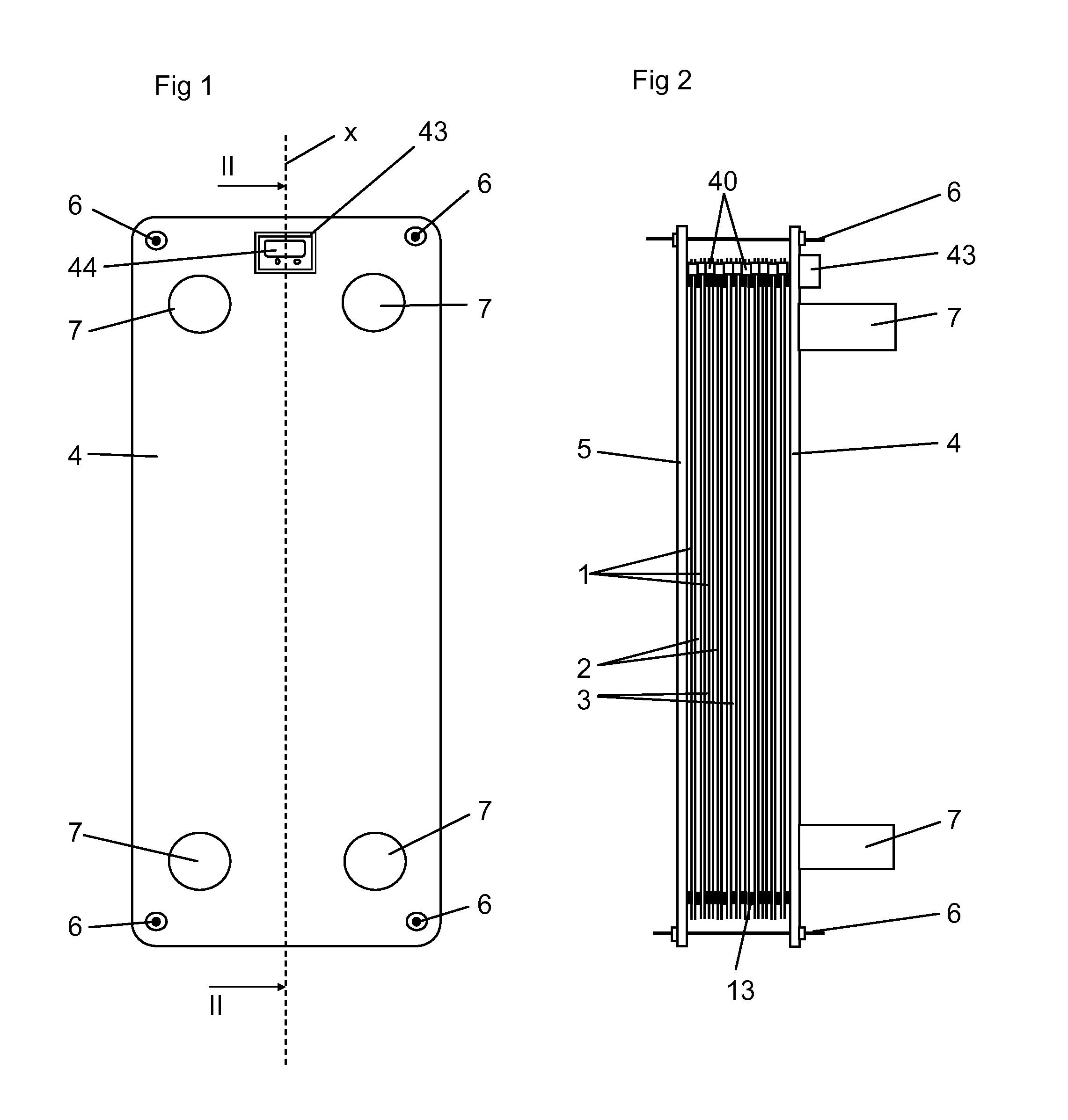
[0045]FIGS. 1 and 2 show a plate heat exchanger comprising a plurality of heat exchanger plates 1 forming a plate package. The heat exchanger plates 1 are arranged beside each other to define several first plate interspaces 2 for a first medium and several second plate interspaces 3 for a second medium. The first plate interspaces 2 and the second plate interspaces 3 are arranged in an alternating order in the plate package. The heat exchanger plates 1 of the plate package are pressed against each other between a frame plate 4 and a pressure plate 5 by means of tie bolts 6. In the embodiments disclosed, the plate heat exchanger comprises four porthole channels 7 forming an inlet and an outlet for the first medium and an inlet and an outlet for the second medium.

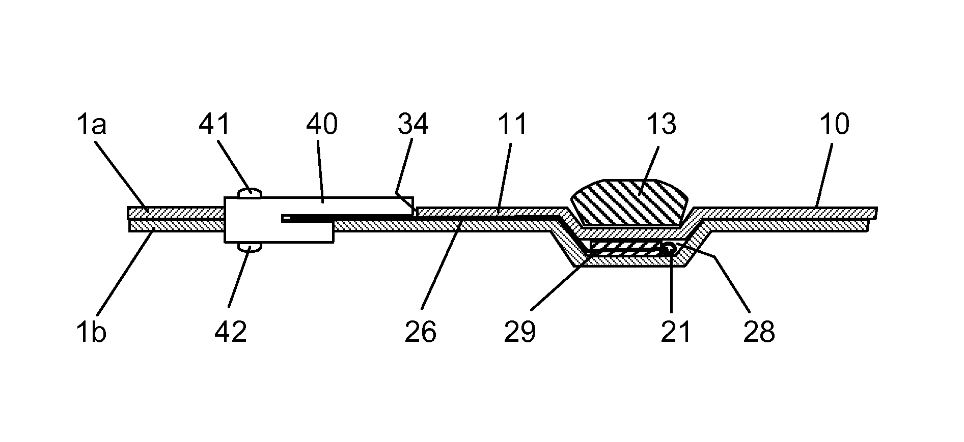
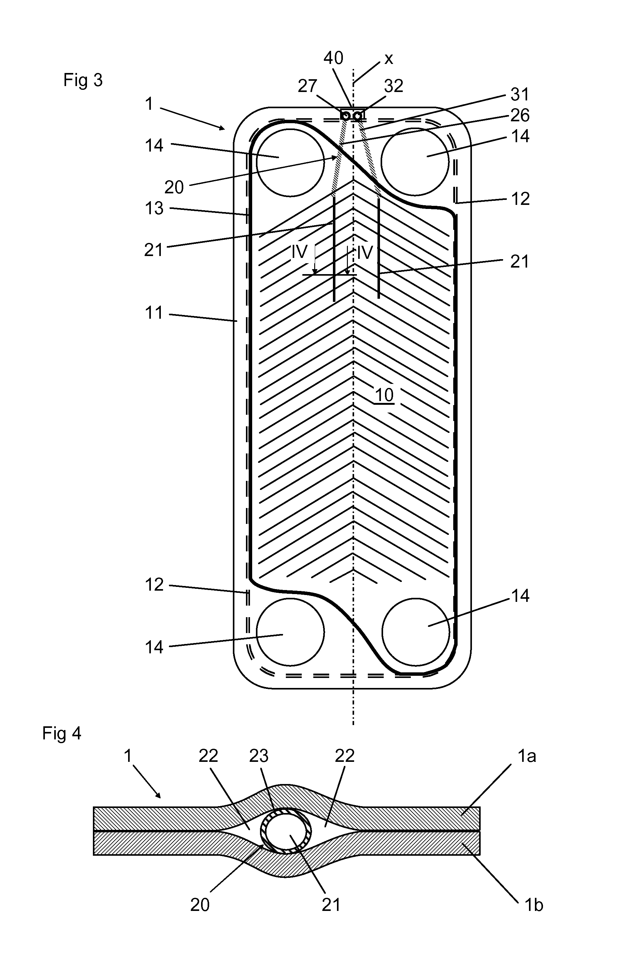
[0046]One of the heat exchanger plates 1 is disclosed in FIG. 3. The heat exchanger plate 1 comprises a heat transfer area 10, an edge area 11, which extends around and outside the heat transfer area 10, and a gasket area 12,...


PUM


Abstract

The invention refers to a plate heat exchanger and a heat exchanger plate. The heat exchanger plate for a plate comprises a heat transfer area and an edge area, extending around the heat transfer area. The heat exchanger plate is a double wall plate formed by two adjoining plates compressed to be in contact with each other. The heat exchanger plate comprises a sensor which is configured to sense at least one parameter and to produce a signal depending on the parameter and that the sensor comprises a sensor probe that is provided between the adjoining plates.

Description

TECHNICAL FIELD OF THE INVENTION[0001]The present invention refers to a heat exchanger plate for a plate heat exchanger, comprising a heat transfer area, and an edge area, which extends around and outside the heat transfer area, wherein the heat exchanger plate is a double wall plate formed by two adjoining plates compressed to be in contact with each other. The invention also refers to a plate heat exchanger comprising a plurality of such heat exchanger plates arranged beside each other to define several first plate interspaces for a first medium and several second plate interspaces for a second medium.BACKGROUND OF THE INVENTION AND PRIOR ART[0002]In plate heat exchangers, where a leak barrier is desired to prevent the media form mixing, it is known to use double wall plates, i.e. plates each comprising two adjoining plates compressed to be in contact with each other. The standard double wall plate gives an additional safety barrier, but normally it is difficult to detect when one...

Claims


Application Information

Patent Timeline
Patent Type & Authority Applications(United States)
IPC IPC(8): F28F27/00G01M3/40F28F3/10
CPCF28F27/00F28F3/10G01M3/40F28F3/083F28F2265/16F28F3/005G01M3/188F28F2265/24F28F3/00F28D9/00F28F1/003F28F3/08
Inventor BERTILSSON, KLASNYANDER, ANDERSJOHANSSONKROZER, ANATOL
Owner ALFA LAVAL CORP AB
Why Eureka
Eureka Blog
Learn More