Orthomode transducer device

Active Publication Date: 2013-08-15
KVH IND INC
View PDF0 Cites 12 Cited by
  • Summary
  • Abstract
  • Description
  • Claims
  • Application Information

AI Technical Summary

Benefits of technology

[0015]In one embodiment, the tapered region includes a second low higher-order mode generation taper shaped and sized to c

Problems solved by technology

The current orthomode couplers are limited in their ability to provide an ext

Method used


Image

  • Orthomode transducer device
  • Orthomode transducer device
  • Orthomode transducer device

Examples


Example

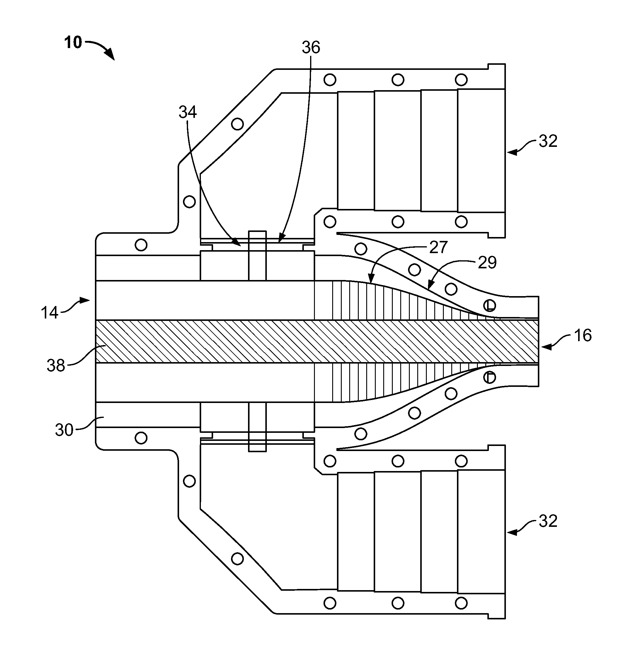
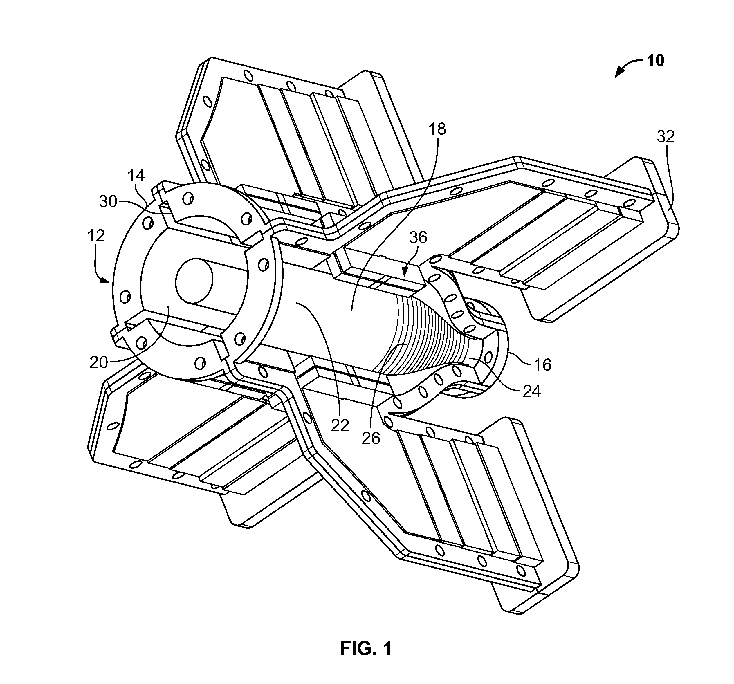
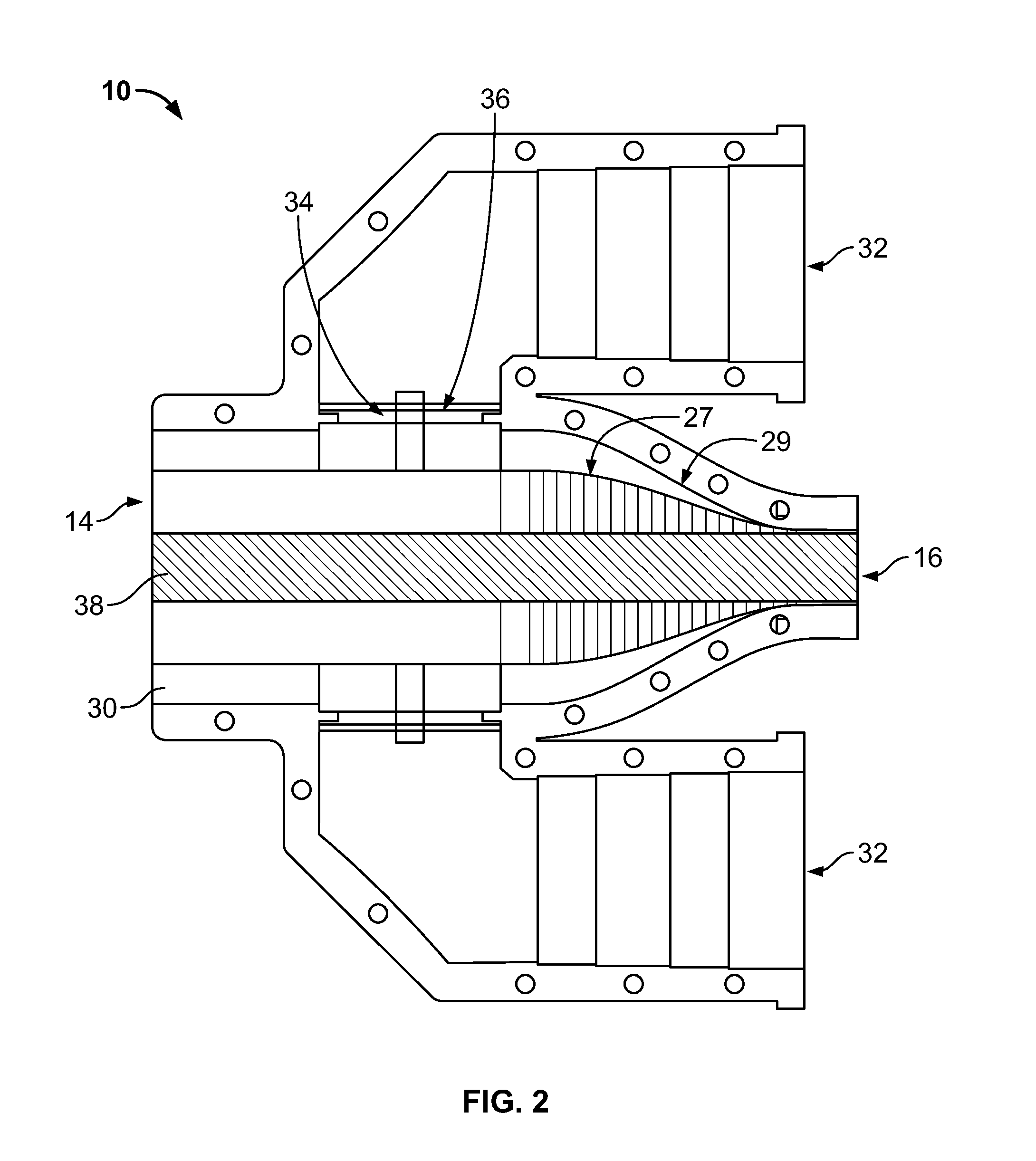
[0021]FIGS. 1, 2 and 3 illustrate various views of an OMT device 10 according to an embodiment of the present invention. The OMT device 10 includes a waveguide structure 12 having a first end 14 and a second end 16. The first end 14 defines a first port for the signals, and the second end 16 defines a second port for signals. The waveguide structure 12 includes an outer wall 18 which defines a waveguide chamber 20 therein. In one embodiment, the outer wall 18 is made of any suitable conductive metal such as aluminum, copper and others. The outer wall 18 has a first cylindrical section 22 proximate the first end 14 and a second cylindrical section 24 proximate the second end 16. The outer wall 18 also includes a region 26 between the first cylindrical section 22 and the second cylindrical section 24. As shown in FIG. 2, the region (a.k.a. tapered region) 26 is tapered such that the outer wall 18 tapers towards the second cylindrical section 24. The region 26 includes a first low high...


PUM


Abstract

The present invention is an orthomode transducer (OMT) device that allows for dual polarized dual frequency band antenna feed systems. The OMT device includes a waveguide structure having a first end and a second end such that the first end defines a port for receiving signals. The waveguide structure includes an outer wall defining a waveguide chamber therein and the outer wall includes a first cylindrical section proximate the first end. The waveguide structure also includes a second cylindrical section proximate the second end and a region therebetween. At least one longitudinal groove is introduced proximate the second end and extends towards the first end of the waveguide structure. The OMT device further includes at least one waveguide coupled to the outer wall of the waveguide chamber which is in signal communication with the waveguide chamber through an opening in the region of the outer wall.

Description

CROSS-REFERENCES[0001]This patent application claims the benefit of U.S. Provisional Application Ser. No. 61 / 596,818 filed Feb. 9, 2012, the contents of which are incorporated by reference hereinFIELD OF THE INVENTION[0002]Embodiments of the invention are generally related to the field of satellite communication and antenna systems, and more particularly to an orthomode transducer device that allows for dual polarized dual frequency band antenna feed systems.BACKGROUND OF THE INVENTION[0003]Satellite antenna systems receive signals from satellites orbiting the earth. The satellite is equipped with an antenna system including a configuration of antenna feeds that receive the uplink signals and transmit the downlink signals to the Earth. Typically, the antenna system includes one or more arrays of feed horns, where each feed horn array includes an antenna reflector for collecting and directing the signals. Many satellite communications systems use the same antenna system and array of ...

Claims


Application Information

Patent Timeline
IPC IPC(8): H01P1/213
CPCH01P1/161
Inventor MONTE, THOMAS D.
Owner KVH IND INC
Why Eureka
Try Eureka