Thin Liquid Crystal Display Device

a liquid crystal display device and thin technology, applied in non-linear optics, instruments, optics, etc., can solve the problems of complicated detachment and mounting process, adverse to the progress of thinning increase the overall thickness of liquid crystal display devices, etc., to facilitate thinning of devices, low cost, easy maintenance

Active Publication Date: 2013-08-15
SHENZHEN CHINA STAR OPTOELECTRONICS TECH CO LTD
View PDF3 Cites 8 Cited by
  • Summary
  • Abstract
  • Description
  • Claims
  • Application Information

AI Technical Summary

Benefits of technology

[0007]An object of the present invention is to provide a thin liquid crystal display device, which arranges a plurality of PCBs in a stacked form to be disposed in a mounting frame that is set at one side of the body of the liquid crystal display device in order to facilitate thinning of the device, easy maintenance, and low cost.

Problems solved by technology

The process of detaching and mounting is complicated and is thus not easy to handle.
Further, the PCBs 300 are arranged behind the liquid crystal display module 200 so that the overall thickness of the liquid crystal display device is increased, this being adverse to the progress of thinning liquid crystal display device.
Although this can reduce the thickness of the display device to some extents, yet the integrated PCBs are of high cost, making it adverse to cost control.

Method used


Image

  • Thin Liquid Crystal Display Device
  • Thin Liquid Crystal Display Device
  • Thin Liquid Crystal Display Device

Examples


Embodiment Construction

[0026]To further expound the technical solution adopted in the present invention and the advantages thereof, a detailed description is given to a preferred embodiment of the present invention and the attached drawings.

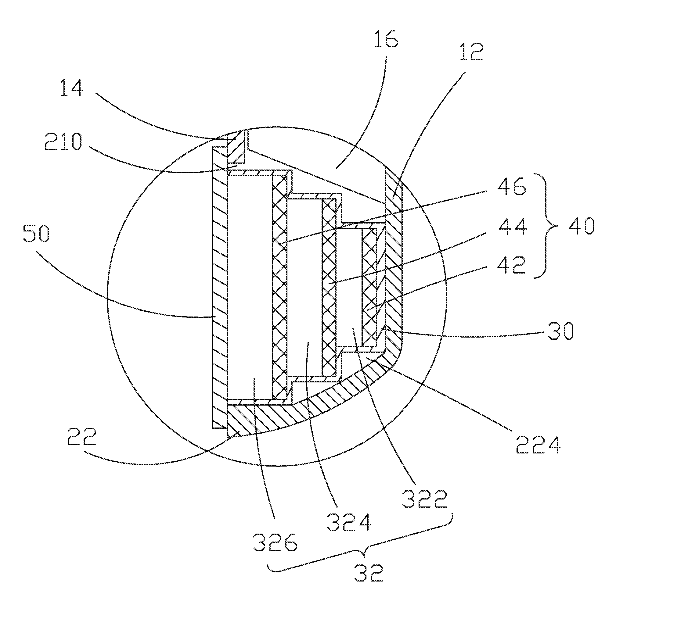
[0027]Referring to FIGS. 3-5, the present invention provides a thin liquid crystal display device, which comprises: a body 10, a mounting seat 20 mounted to the body 10, a mounting frame 30 arranged inside the mounting seat 20, a plurality of printed circuit boards (PCBs) 40 mounted to the mounting frame 30 and electrically connected to the body 10, and a cover plate 50 covering the mounting seat 20.

[0028]The body 10 comprises a front shell 12, a rear shell 14 that is arranged to mate the front shell 12, and a liquid crystal display module 16 arranged between the front shell 12 and the rear shell 14.

[0029]The mounting seat 20 is mounted to the front shell 12 of the body 10 and forms an opening 210 with respect to the body 10. The mounting seat 20 is integrally formed w...


PUM

PropertyMeasurementUnit
sizeaaaaaaaaaa
thicknessaaaaaaaaaa
sizesaaaaaaaaaa

Abstract

The present invention provides a thin liquid crystal display device including a body, a mounting seat mounted to the body, a mounting frame arranged inside the mounting seat, a plurality of circuit boards mounted to the mounting frame and electrically connected to the body, and a cover plate covering the mounting seat. The thin liquid crystal display device of the present invention provides a mounting seat that is mounted to a front shell and located at one side of the body of the liquid crystal display device. The mounting seat receives and retains therein the mounting frame for mounting a plurality of PCBs so that the amount of space required for mounting the PCBs is reduced and overall thinning of the liquid crystal display device is facilitated.

Description

BACKGROUND OF THE INVENTION[0001]1. Field of the Invention[0002]The present invention relates to the field of liquid crystal displaying, and in particular to a thin liquid crystal display device.[0003]2. The Related Arts[0004]Liquid crystal display (LCD) has a variety of advantages, such as small device thickness, low power consumption, and being free of radiation, and is thus widely used.[0005]As shown in FIG. 1, a conventional liquid crystal display device generally comprises a casing 100, a liquid crystal display module 200 arranged inside the casing 100, and a plurality of printed circuit boards (PCBs) 300 arranged inside the casing 100. The casing 100 comprises a front shell 101 and a rear shell (not shown) that mate each other. The liquid crystal display module 200 is mounted to the front shell 101. The plurality of PCBs 300 comprises a liquid crystal driving control PCB 301, a frequency conversion control PCB 302, and an analog-to-digital (ND) conversion PCB 303, which are ar...

Claims


Application Information

Patent Timeline
Patent Type & Authority Applications(United States)
IPC IPC(8): G02F1/1333
CPCG02F2001/13332G02F1/133308G02F1/13332
Inventor QUE, CHENGWEN
Owner SHENZHEN CHINA STAR OPTOELECTRONICS TECH CO LTD
Why Eureka
Try Eureka