System and method for generating and projecting light

a technology of waste storage area and light projection system, which is applied in the direction of lighting and heating equipment, light source combinations, and power sources with built-in, can solve the problems of affecting the image of the event or business providing the facility, affecting the image of the event or business, and ignoring the negative visual experien

Active Publication Date: 2013-08-15
MAXWELL MARK J
View PDF7 Cites 10 Cited by
  • Summary
  • Abstract
  • Description
  • Claims
  • Application Information

AI Technical Summary

Benefits of technology

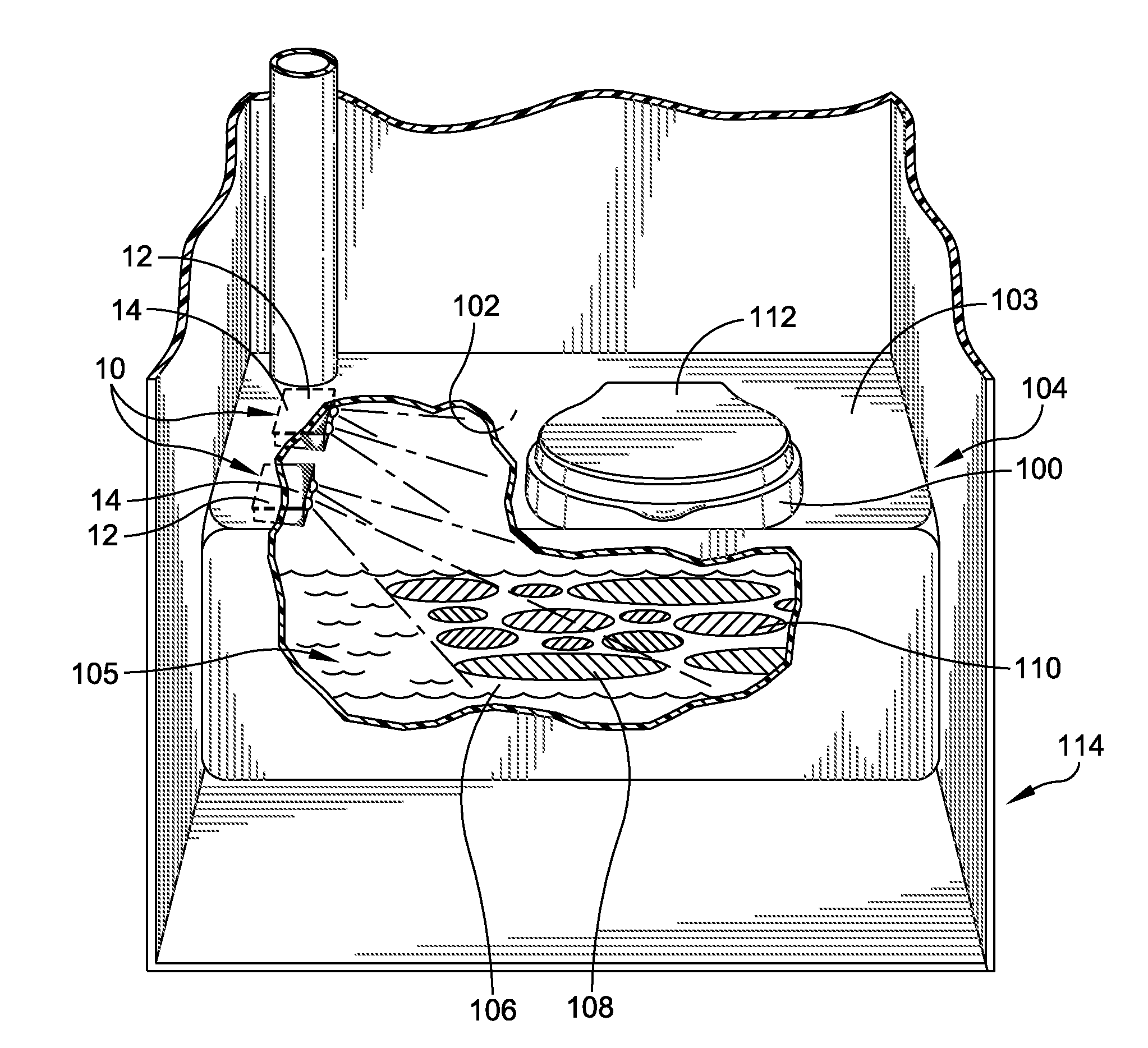
[0011]The present system and method utilizes light in the catch basin or waste storage tank in a toilet or other waste processing or stor

Problems solved by technology

The accumulation of waste matter in these catch basins and storage tanks creates an unpleasant visual experience for the users of these facilities, and results in an overall negative mental image that can impact the image of the event or business providing the facility.
Currently existing products and solutions fail to fully address the negative visual experience that results from observing the accumulation of waste within the catch basin or toilet basin.
While addressing the overall sensory experience of a bathroom visit is of value, the unpleasant visuals that occur upon approaching the toilet itself can negate this initial positive impression.
A further disadvantage is that prior to using the toilet, the lid must be raised, making the negative visual experience nearly unavoidable.
One disadvantage to decorative lids is that they draw attention to the lid, which then leads to a the user of the facilit

Method used


Image

  • System and method for generating and projecting light
  • System and method for generating and projecting light
  • System and method for generating and projecting light

Examples


Embodiment Construction

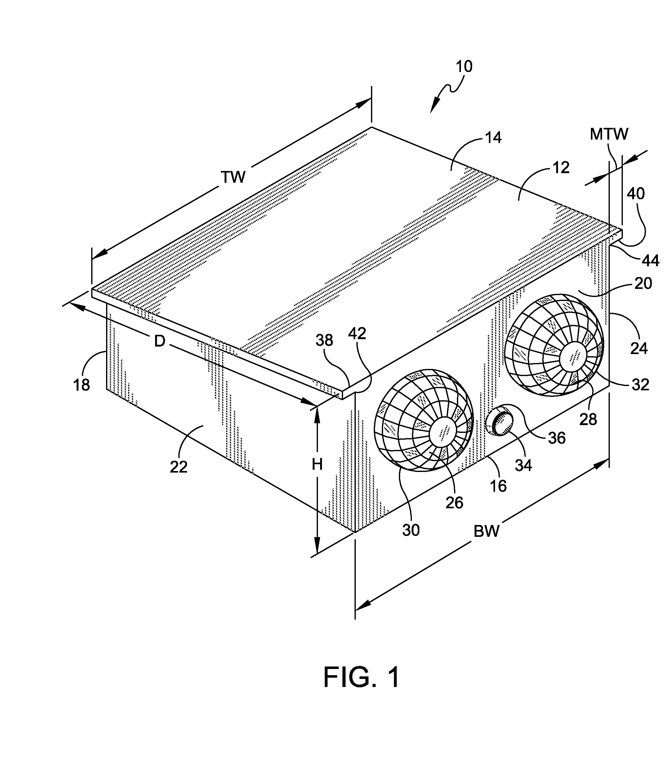
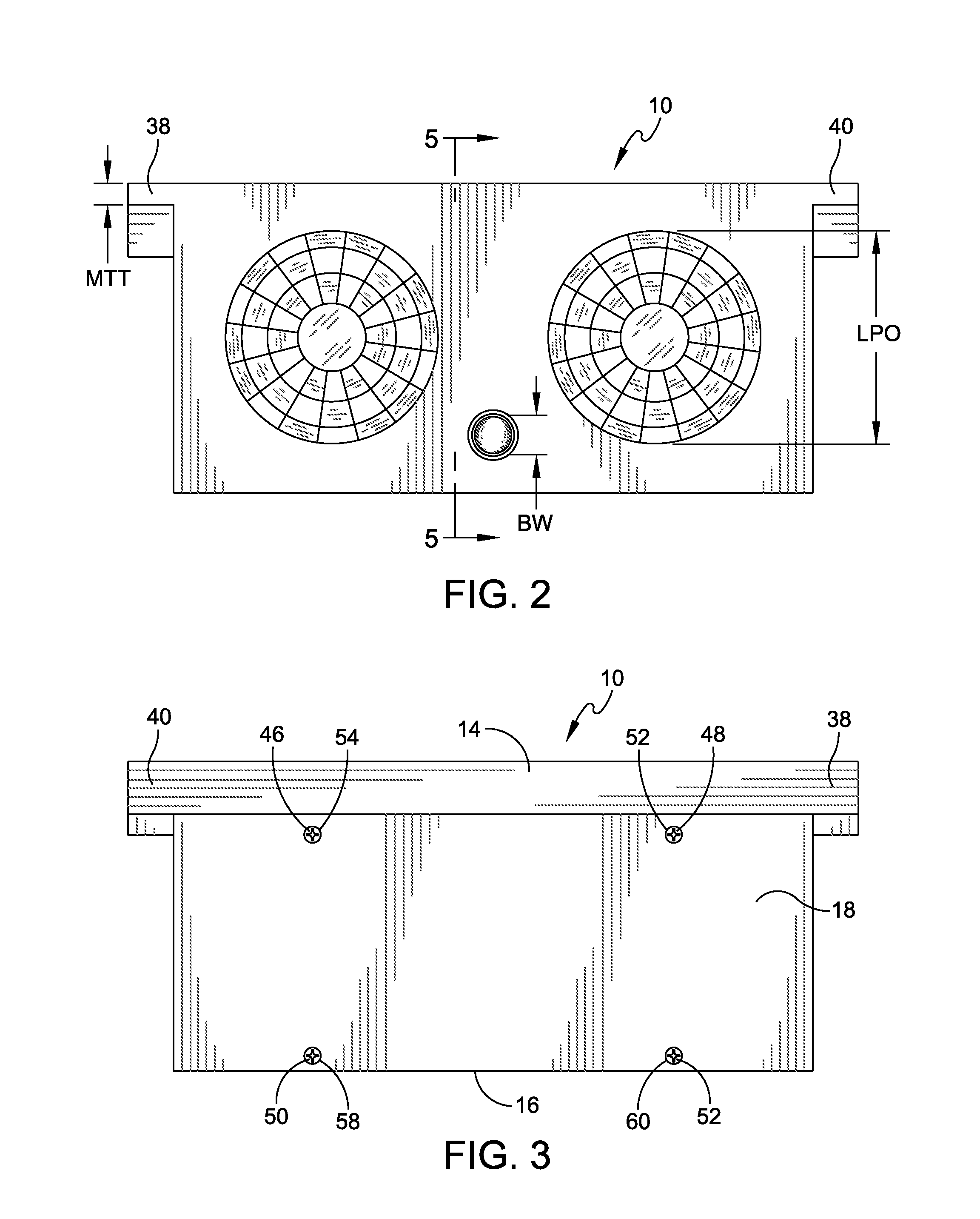
[0036]With reference to FIG. 1, one embodiment of the lighting system, generally 10, has a plastic housing 12 with a planar top side 14, a planar bottom side 16, a planar top side 14 at an acute angle to the plane of the planar top side 16, a planar back side or access panel 18 coplanar with a planar front side 20, and two opposing coplanar lateral sides 22, 24. The back side 18, front side 20, and opposing lateral sides 22, 24 extend between, and perpendicularly from, the top side 14 and bottom side 16 of the housing 12. Two laterally spaced light diffusing but also focusing dome lenses 26, 28 project outwardly from the front side 20 through mating laterally spaced lens passages 30, 32, respectively, penetrating the front, lighting side 18 of the plastic housing 12. In this embodiment, a lighting on-off button 34 projects outwardly from the front side 20 through a mating button passage 36 penetrating the front side 20 of the housing 12.

[0037]The top side 14 is wider than the bottom...


PUM


Abstract

A toilet lighting system and method is disclosed. The lighting system can include a light source directed into a toilet waste container to seek to provide a predetermined lighting effect. One such effect can be to obscure or mask the appearance of waste in the toilet waste container, which, depending on the particular system, can render the user experience less unappealing and even entertaining, more efficient, and/or less wasteful or messy. The light source can be predetermined and mounted to provide various types of effects when material in the toilet waste container is exposed to the light from the light source. The toilet lighting system can be waterproof and capable of being exposed to high fluid pressure when pressure washed. The toilet lighting system can be powered in a number of ways, including by battery, solar, wind, geothermal, or other power supplying systems. Power supplying systems can be switched on and off in any number of ways, including by providing a strobing or intermittent lighting effect. The system can be provided in fixed or portable toilets.

Description

CROSS-REFERENCE TO RELATED APPLICATIONS [0001]The present application claims priority through the applicant's prior provisional patent application, entitled “A METHOD AND SYSTEM FOR GENERATING AND PROJECTING LIGHT IN VARIANT COLORS AND STRUCTURAL PATTERNS,” Ser. No. 61 / 598,479, filed Feb. 14, 2012, which provisional patent application is hereby incorporated by reference in its entirety.FIELD OF INVENTION [0002]The technology of the present application relates to a waste storage area light projection system and method, and more particularly to a system and method for the projection of light within a toilet or toilet waste contact or storage area.BACKGROUND [0003]The use of bathroom facilities is not something that people have traditionally associated with notions of pleasantness. Event organizers, national parks, and all manner of businesses have long been concerned with the experience of using bathroom facilities, both with respect to sanitation as well as to the aesthetics of using...

Claims


Application Information

Patent Timeline
IPC IPC(8): F21V33/00
CPCF21V33/004F21S9/02F21S10/023F21Y2101/02F21Y2113/005F21V23/0435F21K9/65F21Y2115/10F21Y2113/13E03D5/105
Inventor MAXWELL, MARK J.
Owner MAXWELL MARK J
Why Eureka
Try Eureka