Differential phase-contrast imaging

a phase contrast and imaging technology, applied in the field of differential phase contrast imaging, can solve problems such as radiation application

Active Publication Date: 2013-08-15
KONINKLIJKE PHILIPS ELECTRONICS NV
View PDF64 Cites 17 Cited by
  • Summary
  • Abstract
  • Description
  • Claims
  • Application Information

AI Technical Summary

Benefits of technology

[0024]It can be seen as the gist of the invention to provide a diffraction grating with grating portions and aperture portions such that during one image acquisition step, phase-contrast image information can be recorded as well as density information. Thus, an increased degree of radiation passing the object, for example a patient, can be used for recording image data. As a further advantage, simply said, two different types of information, i.e. two different image types are recorded, namely phase-contrast image information as well as density information, e.g. conventional X-ray images. Of course, also the gratings portions provide some information about the mean attenuation, e.g. by averaging over the phase stepping scans. By translating the phase grating and the analyzer grating according to the invention to a second position, the analyzer grating having X-ray absorbing bars, those sensor areas or sensor pixels which have recorded phase information in the first acquisition step are now covered with the aperture portions such that these pixels can now record density information, whereas the pixels that have

Problems solved by technology

It has been shown that the amount of X-ray radiation being applied to the object, for example a patient, is p

Method used


Image

  • Differential phase-contrast imaging
  • Differential phase-contrast imaging
  • Differential phase-contrast imaging

Examples


Embodiment Construction

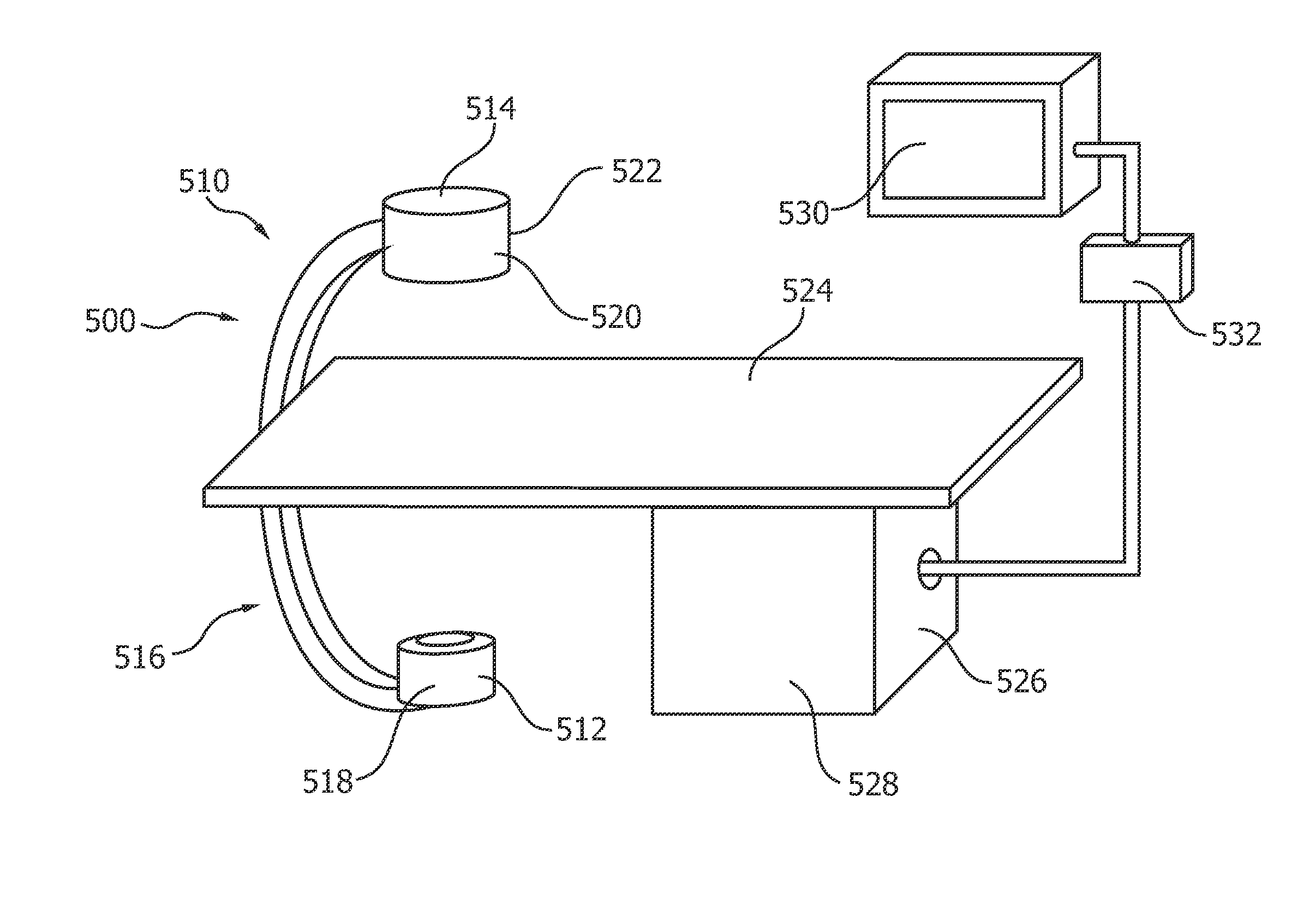
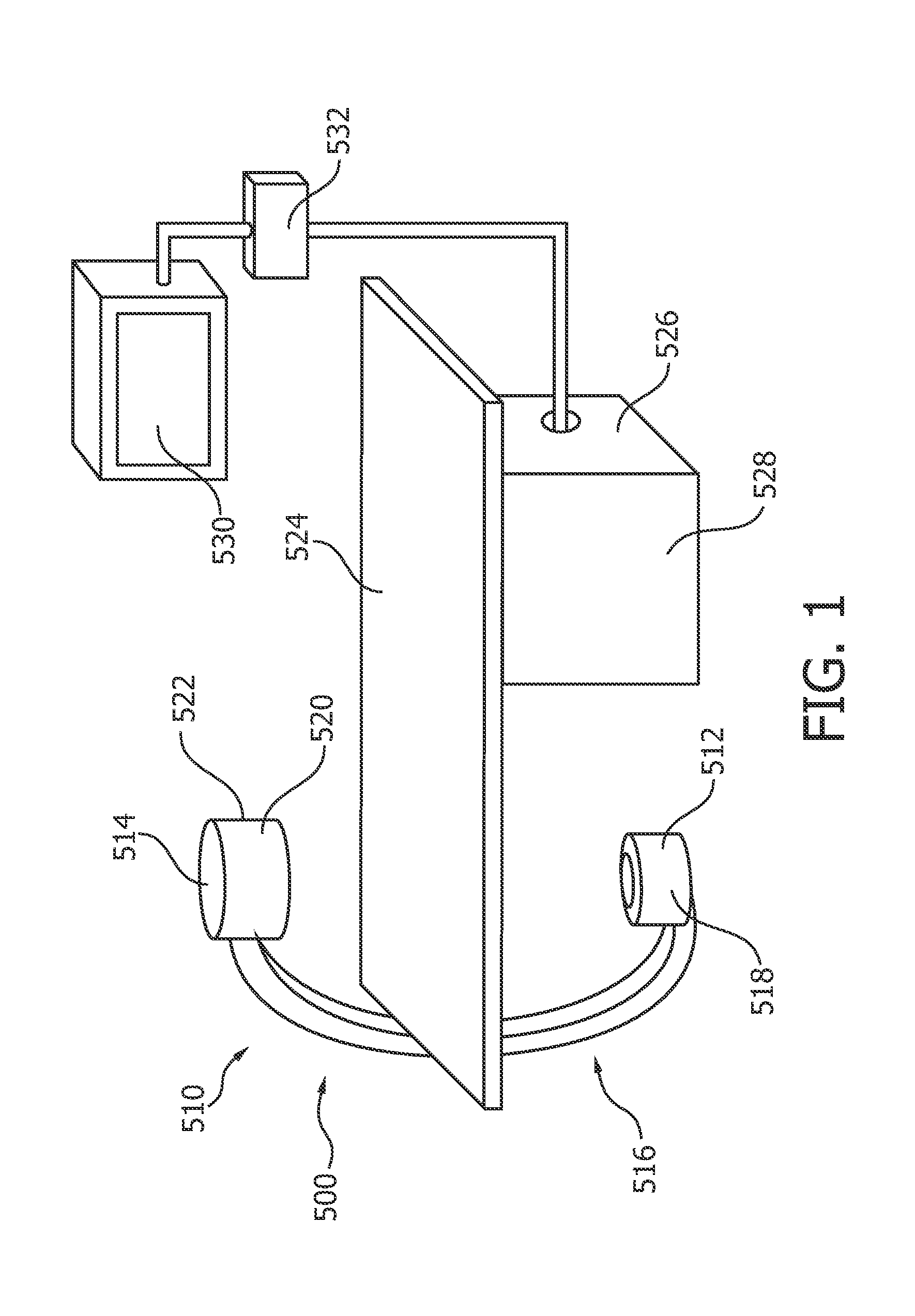
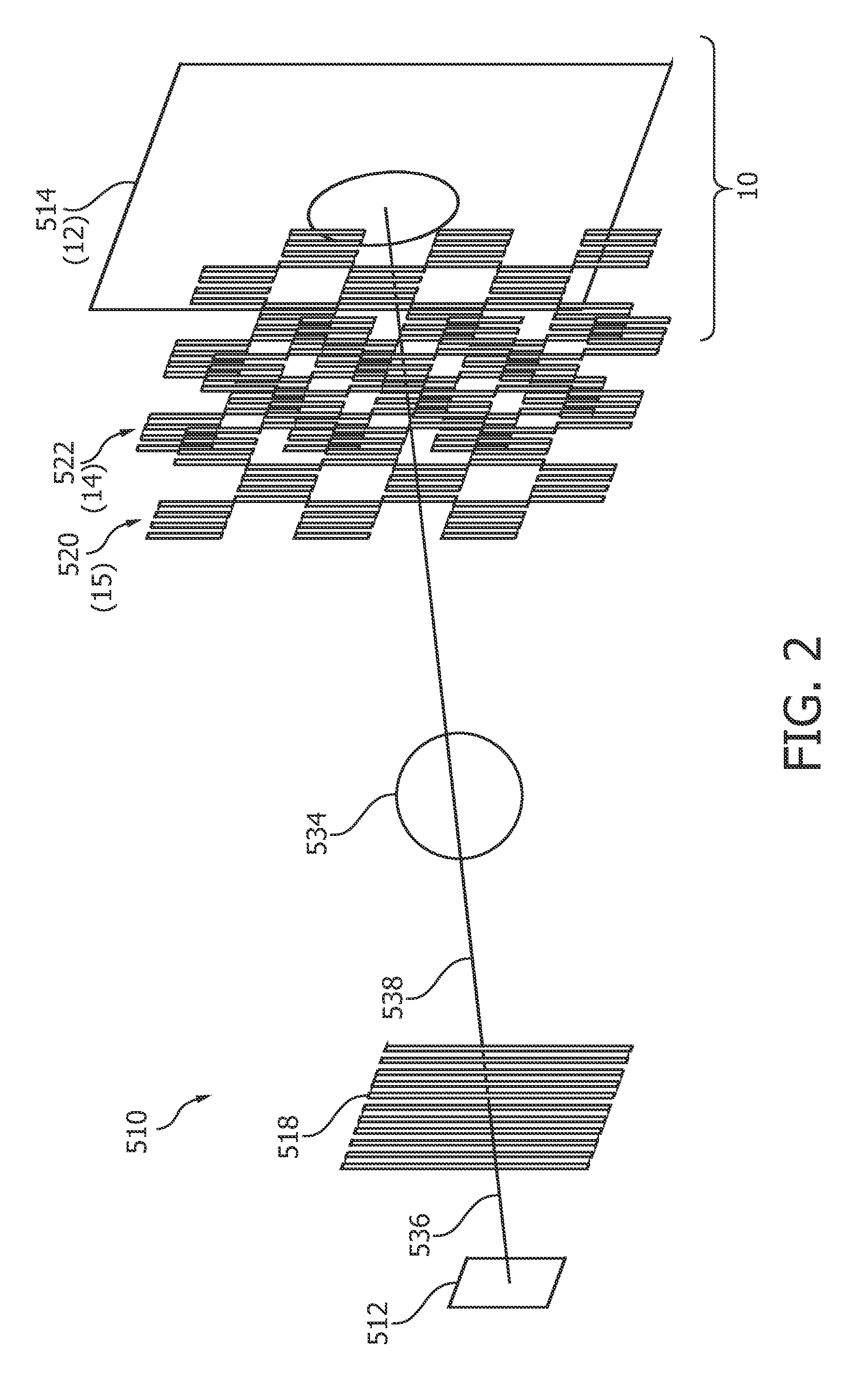
[0037]FIG. 1 schematically shows a medical X-ray imaging system 500 for differential phase-contrast imaging. The system comprises an X-ray image acquisition device 510 for generating phase-contrast images of an object, for example a patient. The X-ray image acquisition device 510 comprises an X-ray source 512 and a detector 514 arranged opposite to the X-ray source on a C-arm structure 516. Further, the X-ray image acquisition device 510 comprises a source grating 518 (not further shown), a phase grating 520 and an analyzer grating 522 which are also not further shown. These aspects will be described in more detail with reference to FIG. 2 below.

[0038]A table 524 is provided as an object receiving device. The table 524 is arranged at least partially between the X-ray source 512 and the detector 514.

[0039]Further, a processing unit 526 and an interface unit 528 (not further shown) are also provided. Still further, a display device 530 is arranged above the table to display informatio...


PUM


Abstract

The present invention relates to differential phase-contrast imaging, in particular to a structure of a diffraction grating, e.g. an analyzer grating and a phase grating, for X-ray differential phase-contrast imaging. In order to make better use of the X-ray radiation passing the object, a diffraction grating (14) for X-ray differential phase-contrast imaging is provided with at least one portion (24) of a first sub-area (26) and at least one portion (28) of a second sub-area (30). The first sub-area comprises a grating structure (54) with a plurality of bars (34) and gaps (36) being arranged periodically with a first grating pitch P G (38), wherein the bars are arranged such that thy change the phase and/or amplitude of an X-ray radiation and wherein the gaps are X-ray transparent. The second sub-area is X-ray transparent and wherein the at least one portion of the second sub-area provides an X-ray transparent aperture (40) in the grating. Portions of the first and second sub-areas are arranged in an alternating manner in at least one direction (42).

Description

FIELD OF THE INVENTION[0001]The present invention relates to differential phase-contrast imaging, in particular to diffraction gratings for X-ray differential phase-contrast imaging, a detector arrangement of an X-ray system for generating phase-contrast images of an object, an X-ray image acquisition device for generating phase-contrast images of an object, a medical X-ray imaging system for differential phase-contrast imaging, a method for differential phase-contrast imaging as well as a computer program element and a computer-readable medium.BACKGROUND OF THE INVENTION[0002]Differential phase-contrast imaging is used, for example, to enhance the contrast of low absorbing specimen, compared to conventional amplitude contrast images. In EP 1 731 099 A1, an X-ray interferometer arrangement is described comprising a standard polychromatic X-ray source, a source grating, a beam splitter grating and an analyzer grating and an image detector. An object is arranged between the source gra...

Claims


Application Information

Patent Timeline
IPC IPC(8): G21K1/06G01N23/04G01T7/00
CPCA61B6/4441A61B6/484G01N23/04G01N2223/064G01T7/00G01N2223/612G21K1/06A61B6/4092A61B6/4291G01N2223/1016G01N23/041G21K1/067
Inventor ROSSL, EWALD
Owner KONINKLIJKE PHILIPS ELECTRONICS NV
Why Eureka
Try Eureka