Sliding component

a technology of sliding components and components, applied in the direction of shafts, bearings, engine seals, etc., can solve the problems of increased leakage rate, increased friction coefficient, and increased possibility of surface abrasion or damage due to direct contact, so as to achieve significant reduction of leakage rate, shorten machining time, and easy disposal

Active Publication Date: 2013-08-15
EAGLE INDS
View PDF7 Cites 72 Cited by
  • Summary
  • Abstract
  • Description
  • Claims
  • Application Information

AI Technical Summary

Benefits of technology

[0067]The present invention achieves excellent effects such as those below.
[0068](1) According to the first through sixth aspects, there is no leakage when no motion is occurring, the pressure gradient ∂p/∂r in the low-pressure side (the internal peripheral side) of the sliding surface can be made negative during usual times including the start of relative sliding, and as a result, Q in formula I can be made negative. Specifically, a pumping action occurs from the low-pressure side of the sliding surface toward the high-pressure fluid side, and the leakage rate can therefore be significantly reduced. Furthermore, according to the third and fifth aspects, since there is more space than in cases in which both a Rayleigh step mechanism and a reverse Rayleigh step mechanism are provided to the same sliding surface, the mechanisms are easily disposed in the sliding surfaces, and machining time can be shortened.
[0069]According to the fourth aspect, the fluid used for lubrication is not susceptible to the effects of centrifugal force from rot...

Problems solved by technology

Consequently, in a seal used in an environment where contact causes immediate surface damage such as scorching, the result of prioritizing the dynamic pressure effect is that the liquid membrane thickness h increases and the leakage rate therefore increases.
In a seal used in an environment in which direct contact does not readily cause problems even over a long period of time, the result of prioritizing sealing performance is that the gap h is small, the dynamic pressure effect is also small, and there is therefore a higher possibility of surface abrasion or damage due to direct contact, and a higher frictional coefficient.
In this mechanism, the structure is complicated because an initial gap must be provided mechanically, and since the gap is also present when no motion is occurring, a problem is encountered in that leakage occurs when no motion is occurring.
In this structure, since dynamic pressure is not generate...

Method used


Image

  • Sliding component
  • Sliding component
  • Sliding component

Examples


embodiment 1

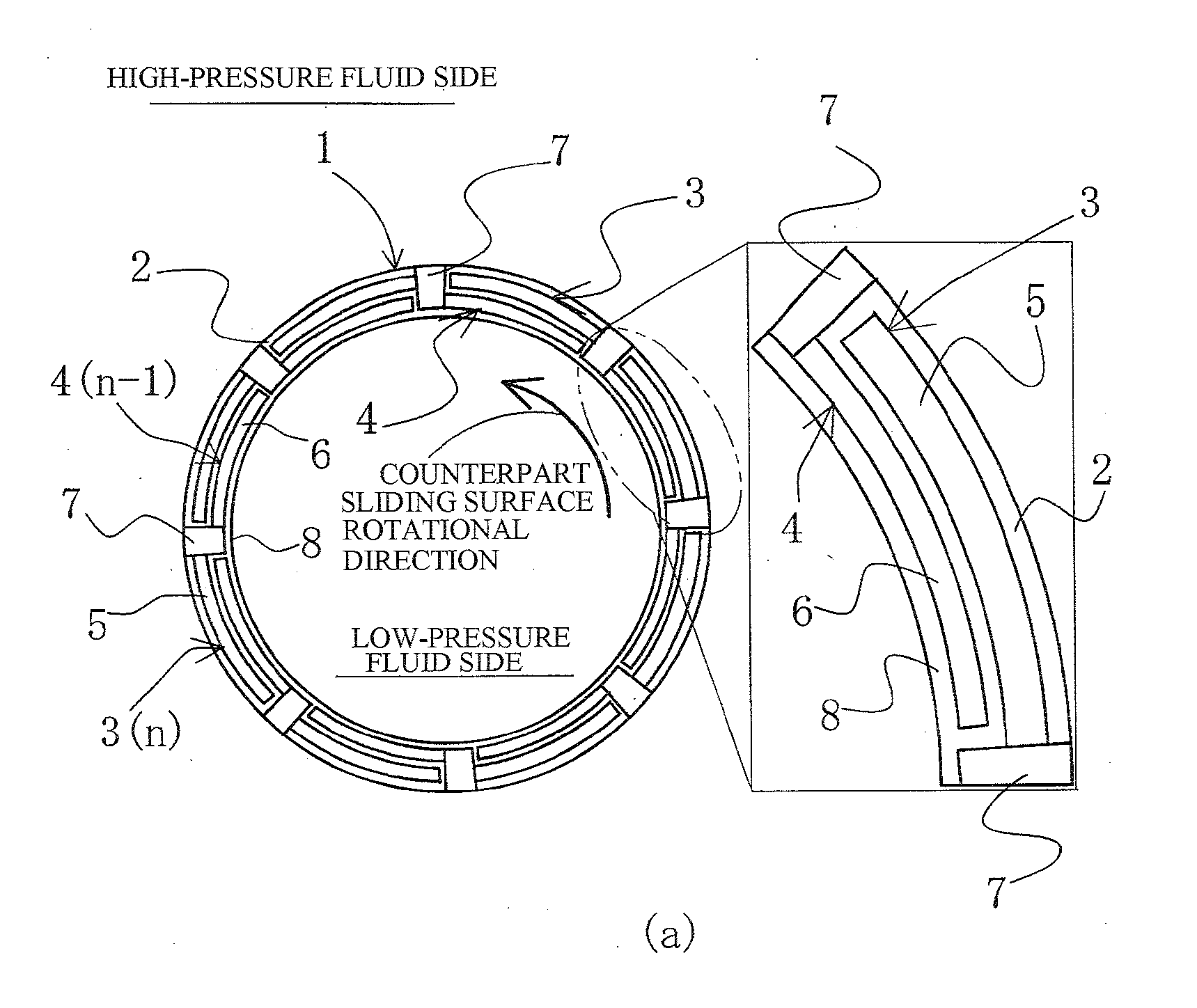
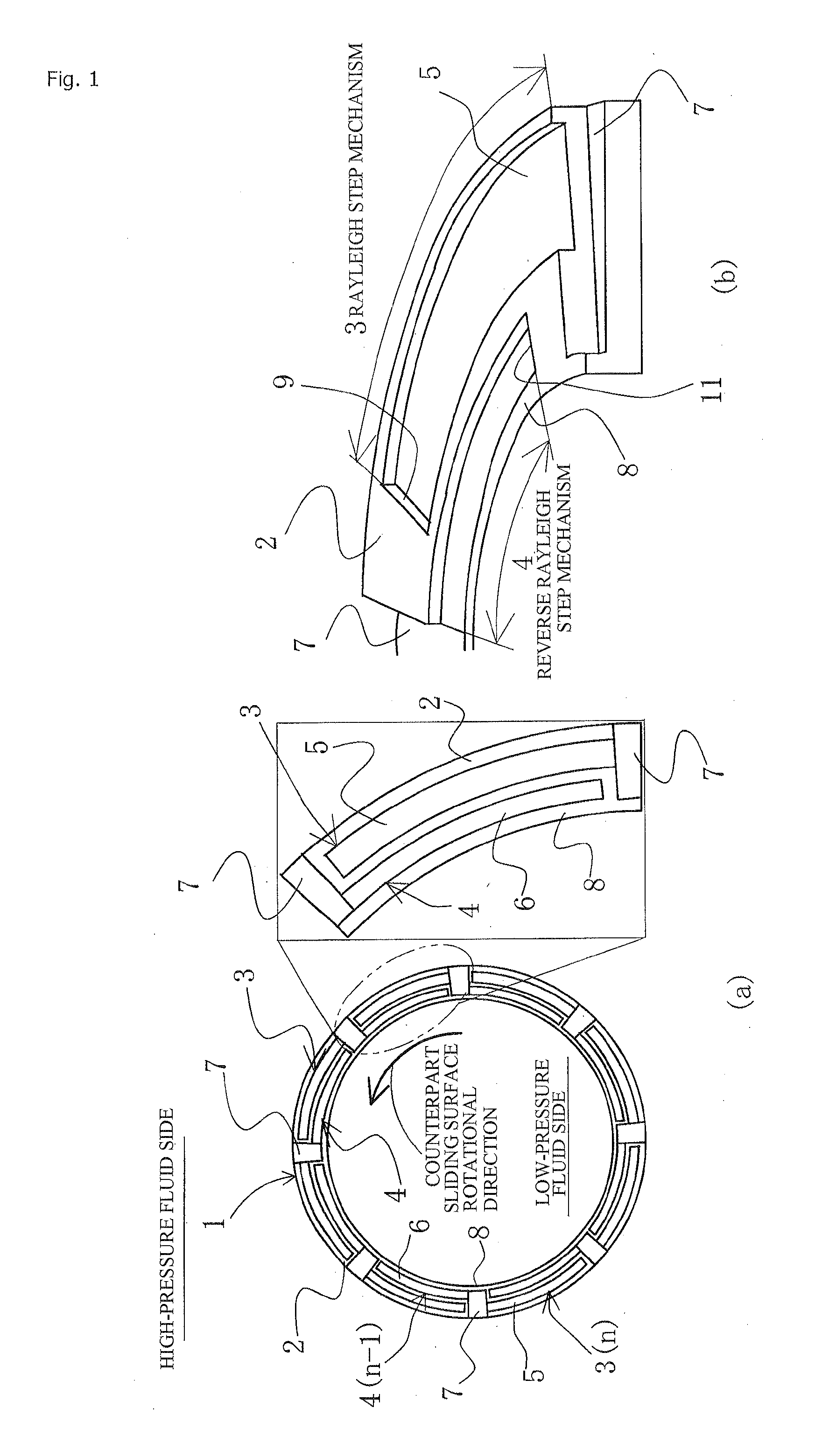
[0109]FIG. 1 illustrates a sliding surface 2 of a sliding component 1 according to Embodiment 1 of the present invention, wherein (a) is a plan view of the sliding surface 2 and (b) is a perspective view showing an enlargement of part of the sliding surface 2.

[0110]In FIG. 1, the sliding component 1 is an annular body, wherein usually a high-pressure sealed fluid is present on either the internal or external periphery of the sliding surface 2 of the sliding component 1, and the other periphery is exposed to the atmosphere.

[0111]This sealed fluid can be effectively sealed using the sliding component 1. The sliding component 1 is used in both a rotation sealing ring and a fixing sealing ring constituting a pair in a mechanical sealing device, for example. The sliding surface of the rotation sealing ring and the sliding surface of the opposing fixing sealing ring are brought in close contact, and a sealed fluid present on either the internal or external periphery of the sliding surface...

embodiment 2

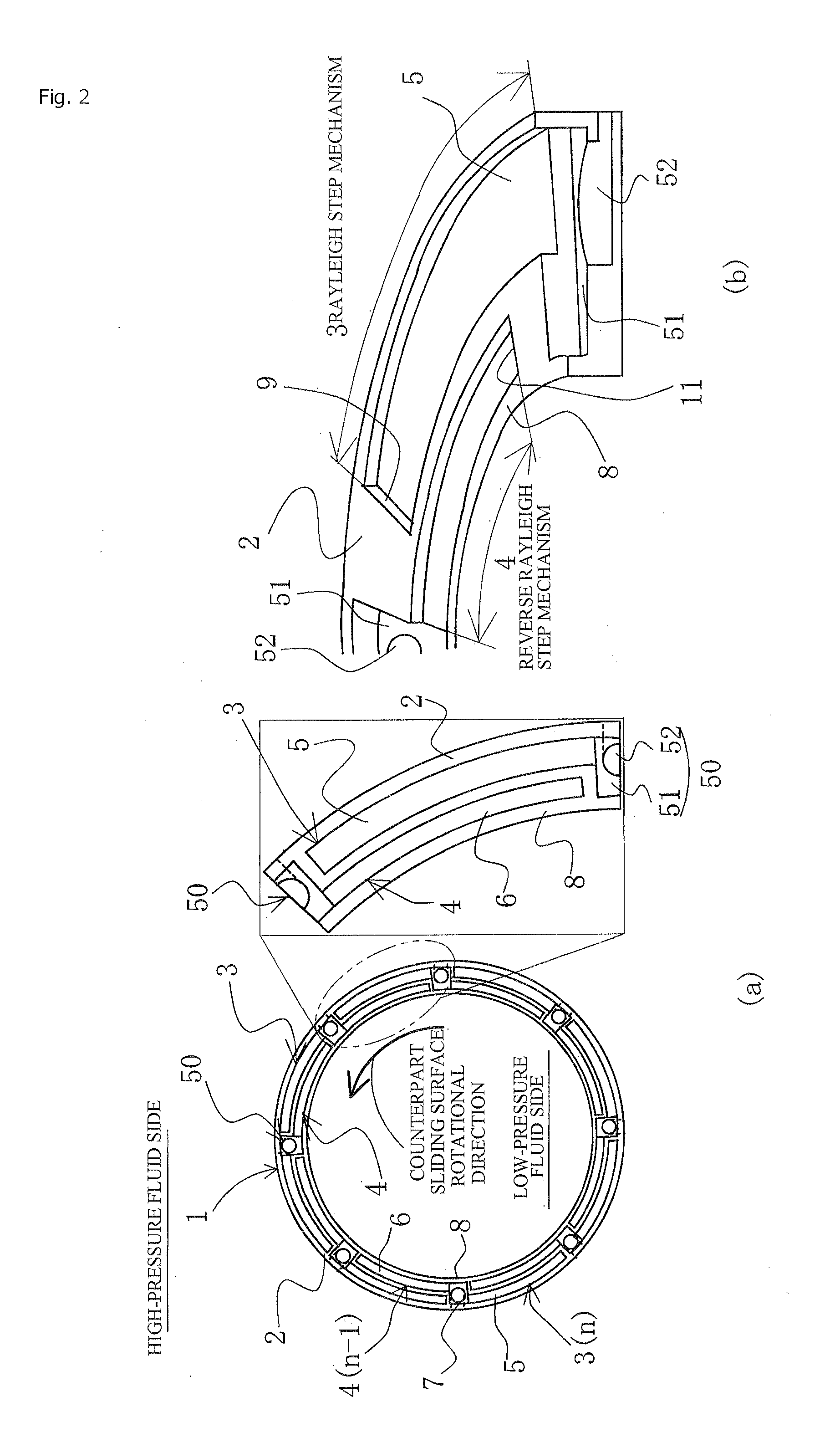
[0159]FIG. 13 is for describing the sliding surface 2 of the sliding component 1 according to Embodiment 2 of the present invention, wherein (a) is a plan view of the sliding surface 2 and (b) is a perspective view showing an enlargement of part of the sliding surface 2.

[0160]In FIG. 13, the same symbols as those of Embodiment 1 indicate the same members as Embodiment 1, and detailed descriptions are omitted. In FIG. 13, the rotational direction of the counterpart sliding component opposing the annular sliding component 1 is a counterclockwise direction. This is the same even if the sliding component 1 rotates in a clockwise direction.

[0161]The external peripheral side of the sliding surface 2 of the sliding component 1 is provided with a positive pressure generating groove 3 composed of a Rayleigh step mechanism, a modified Rayleigh step mechanism, a spiral groove, a dimple, or the like; and the internal peripheral side is provided with a negative pressure generating mechanism 4 co...

embodiment 3

[0195]FIG. 21 is for describing the sliding surface 2 of the sliding component 1 according to Embodiment 3 of the present invention, wherein (a) is a plan view of the sliding surface 2 and (b) is a perspective view showing an enlargement of part of the sliding surface 2.

[0196]In FIG. 21, the same symbols as those of Embodiments 1 and 2 indicate the same members as Embodiments 1 and 2, and detailed descriptions are omitted. In FIG. 21, the rotational direction of the counterpart sliding component opposing the annular sliding component 1 is a counterclockwise direction. This is the same even if the sliding component 1 rotates in a clockwise direction.

[0197]In Embodiment 1 described above, the concept that the smaller the number of reverse Rayleigh step mechanisms 4 (the smaller the number of radial-direction grooves 7) and the greater the width w of the internal-peripheral-side seal surface 8, the lower the leakage rate, is as described in Embodiment 1 and so forth. Needless to say, h...


PUM


Abstract

A positive pressure generating mechanism comprising a positive pressure generating groove is provided to a high-pressure side of one of two sliding surfaces that slide relative to each other in a pair of sliding components, and a negative pressure generating mechanism comprising a negative pressure generating groove is provided to a low-pressure side. The positive pressure generating groove and negative pressure generating groove are communicated with a high-pressure fluid side and separated from a low-pressure fluid side by a seal surface.

Description

TECHNICAL FIELD[0001]The present invention relates to a sliding component applied to a mechanical seal, a bearing, or another sliding part, for example. The present invention particularly relates to a sliding component of a sealing ring, a bearing, or the like, in which a fluid is present on sliding surfaces to reduce friction, and the fluid must be prevented from leaking out from the sliding surfaces.BACKGROUND ART[0002]In a mechanical seal, which is one example of a sliding component, the contrary conditions “sealing” and “lubrication” must both be achieved in order to maintain airtightness over a long period of time. Particularly, in recent years there has been a rising demand for less friction in order to prevent leakage of sealed fluid and reduce mechanical loss, for the sake of environmental measures and the like. The means of reducing friction can be achieved by creating a so-called fluid lubrication state, in which dynamic pressure is generated by rotation between sliding su...

Claims


Application Information

Patent Timeline
IPC IPC(8): F16C32/06F16J15/40
CPCF16C17/045F16C17/047F16C33/741F16C33/74F16C32/0633F16J15/40F16J15/3412F16J15/342F01D25/168F01D25/186
Inventor TOKUNAGA, YUICHIRO
Owner EAGLE INDS
Why Eureka
Try Eureka