Eureka AIR delivers breakthrough ideas for toughest innovation challenges, trusted by R&D personnel around the world.

Blower assembly

Active Publication Date: 2013-08-15
HANON SYST
View PDF7 Cites 15 Cited by
  • Summary
  • Abstract
  • Description
  • Claims
  • Application Information

AI Technical Summary

Benefits of technology

The present invention provides a blower assembly that minimizes cost, airflow restriction, and complexity, while maximizing efficiency. The assembly includes a housing and a fan wheel rotating a volume of air. The fan wheel has outer blades that are coupled to the hub and inner and outer rings, and an inner surface of the housing and an outer surface of the fan wheel form a scroll duct to receive the fluid. The scroll duct expands in both the axial and radial directions from a scroll cutoff to the fluid outlet. This design allows for efficient airflow and reduces the impact of airflow restrictions.

Problems solved by technology

However, current centrifugal blowers consume significant electrical energy which negatively affects a fuel economy of the vehicle.
Further, during high load operating conditions of the vehicle, energy consumption of the HVAC system generally accounts for a significant portion of the available electrical energy of the vehicle.
Current centrifugal blowers also produce inadequate air flow during extreme driving conditions for a desired customer comfort level.

Method used


Image

  • Blower assembly
  • Blower assembly
  • Blower assembly

Examples


Embodiment Construction

[0017]The following detailed description and appended drawings describe and illustrate various exemplary embodiments of the invention. The description and drawings serve to enable one skilled in the art to make and use the invention, and are not intended to limit the scope of the invention in any manner.

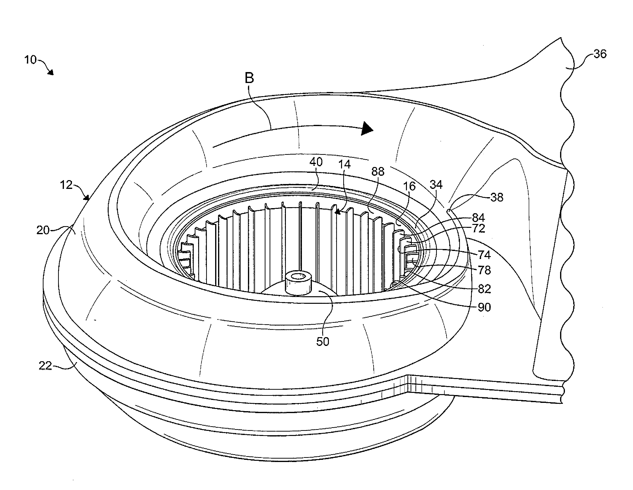
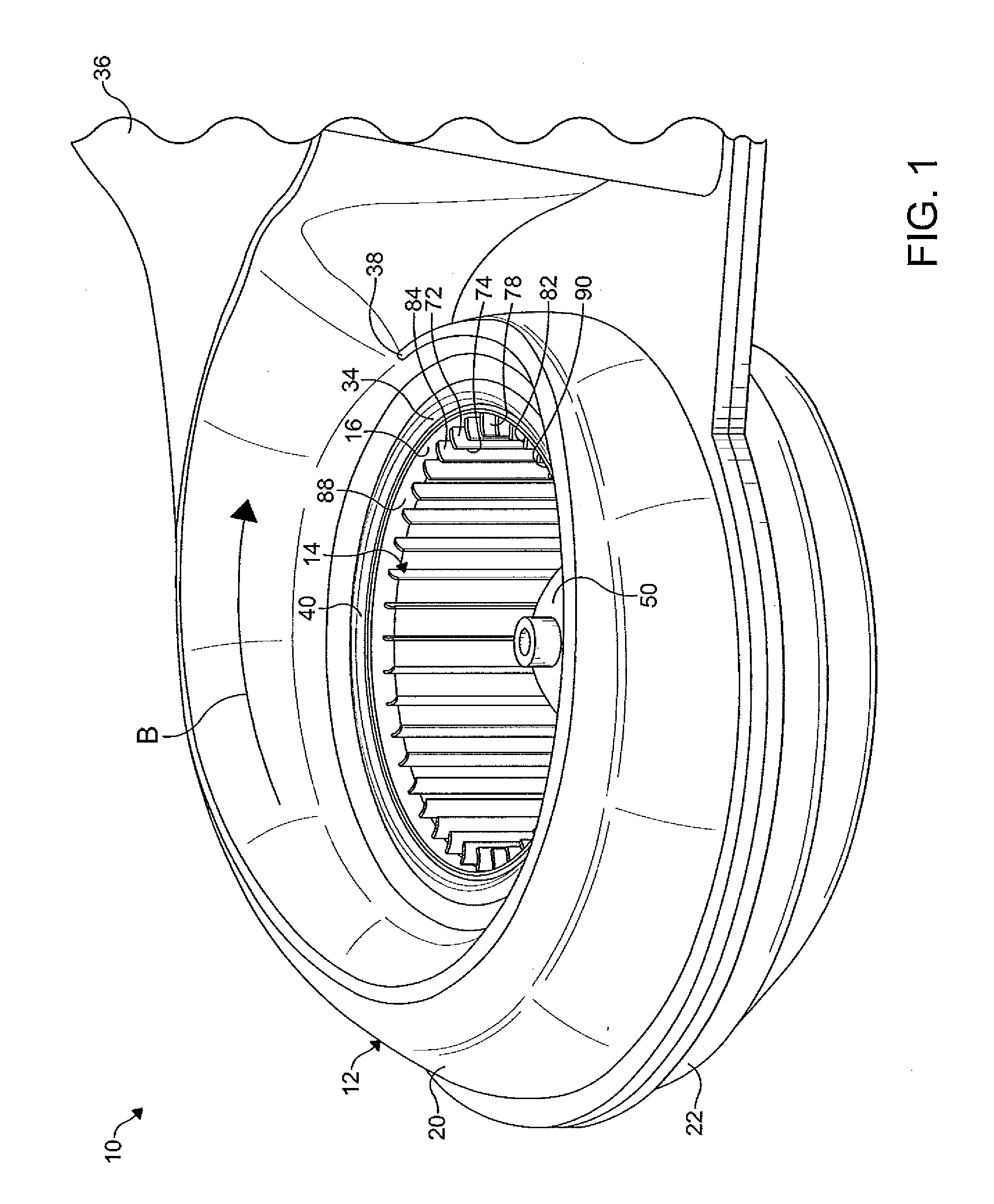
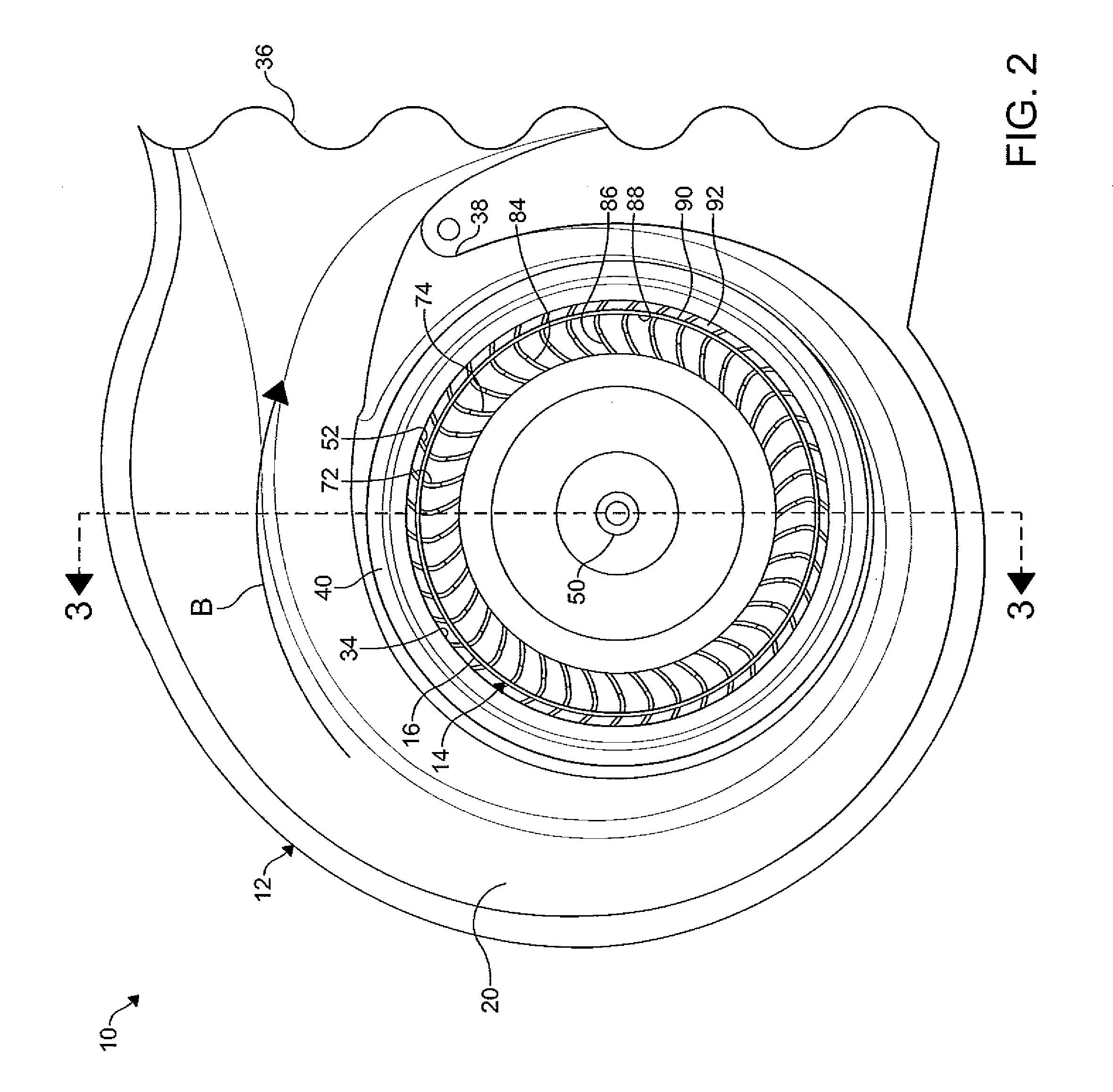
[0018]FIGS. 1-4 show a blower assembly 10 according to the present invention. The blower assembly 10 includes a housing 12, a centrifugal fan wheel 14 having concentrically arranged inner and outer annular rings 16, 18, and a motor (not shown) for causing a rotation of the fan wheel 14. The blower assembly 10 is used for an air conditioning unit of a vehicle (not shown). It is understood that the blower assembly 10 can be used in other applications as desired. Although the housing 12 and the fan wheel 14 shown are formed from plastic, it is understood that the housing 12 and fan wheel 14 can be formed from other materials as desired.

[0019]In certain embodiments, the housing 12 includ...


PUM


Abstract

A blower assembly for use in a vehicle is disclosed, wherein the blower assembly includes a housing and a fan wheel disposed in the housing. A scroll duct formed in the housing axially and radially expands from a scroll cutoff towards an air outlet. The fan wheel includes a hub, concentrically arranged inner and outer annular rings, and an array of spaced apart blades extending between the hub and the annular rings.

Description

FIELD OF THE INVENTION[0001]The invention relates to a blower assembly and more particularly to a blower assembly which optimizes efficiency and minimizes noise and vibration during an operation thereof.BACKGROUND OF THE INVENTION[0002]Centrifugal fans or blowers are commonly used for directing a forced flow of air through an air duct. In a typical blower assembly, air is drawn into a housing through an air inlet and discharged from the housing through an air outlet. Blower assemblies typically include an electrically driven fan wheel that rotates in a predetermined direction in the housing. The fan wheel includes one or more curved blades, which draw the air into the fan wheel axially along an axis of rotation and discharge the air radially outwardly therefrom.[0003]Typically, in climate control applications such as heating, ventilating, and air conditioning (HVAC) systems of a vehicle, the centrifugal blowers are required to operate effectively and efficiently over a range of oper...

Claims


Application Information

Patent Timeline
IPC IPC(8): F04D17/08F04D29/44
CPCF04D25/08F04D29/4226F04D29/162F04D29/282F04D29/4213
Inventor IYER, JAYANTHI R.HAUPT, ERIC KEITHVERMETTE, DENNIS ANTHONY
Owner HANON SYST
Why Eureka
Eureka Blog
Learn More