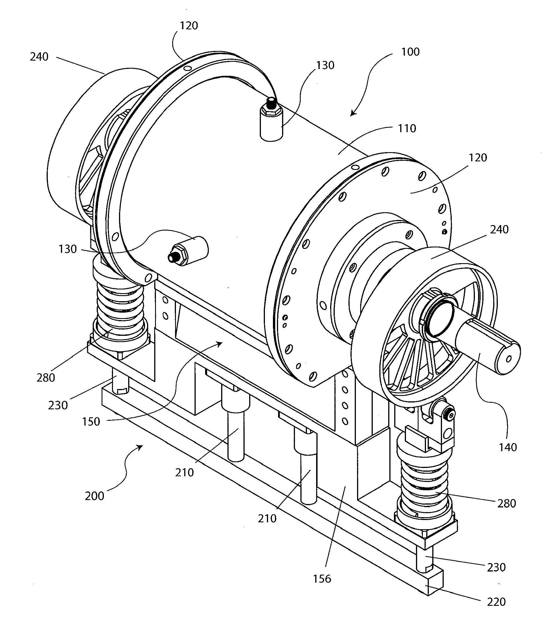
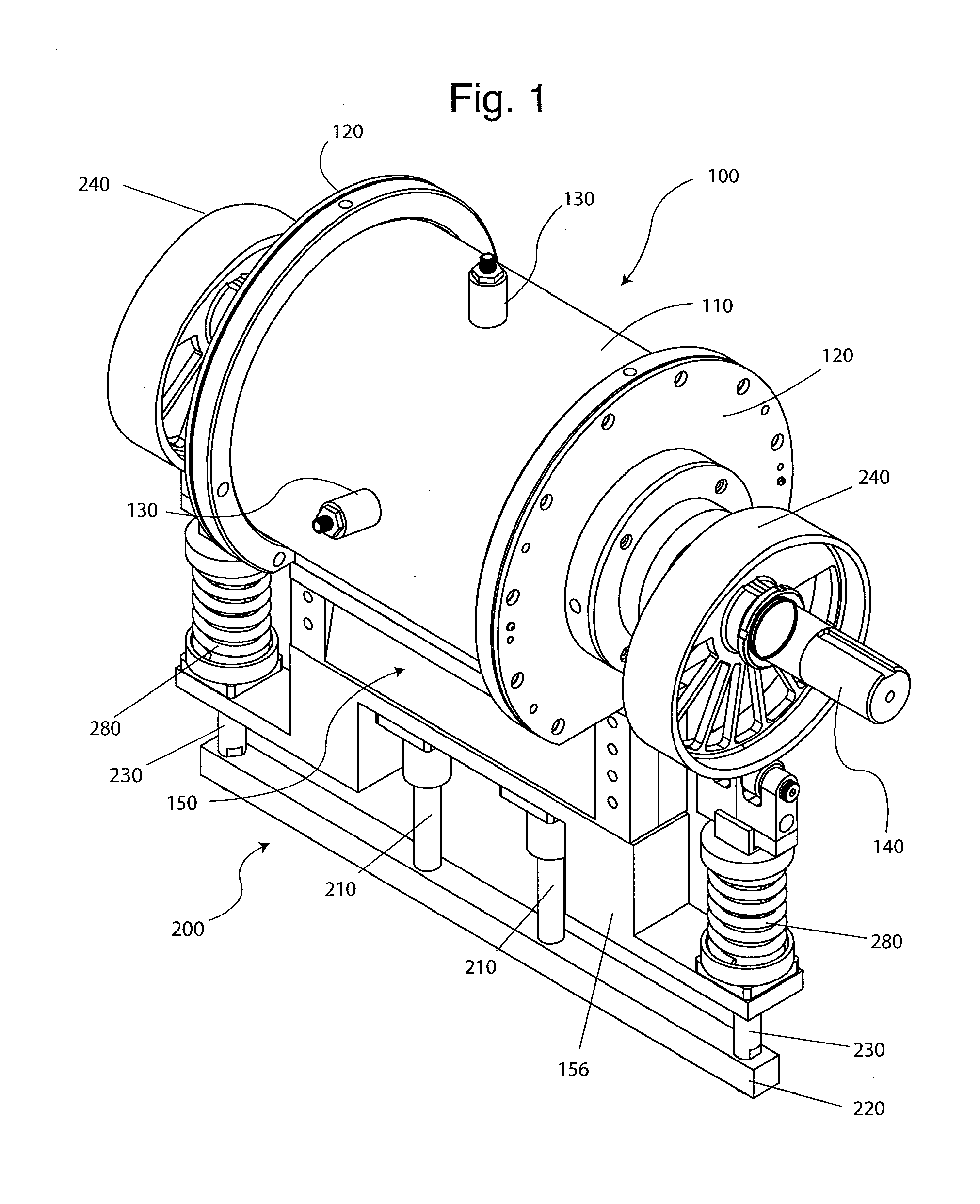
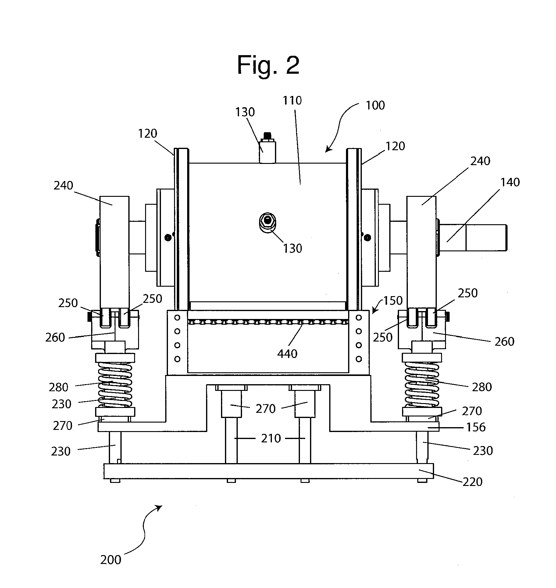
Compressor with liquid injection cooling
a technology of liquid injection cooling and compressor, which is applied in the direction of liquid fuel engines, machine/engines, rotary/oscillating piston pump components, etc., can solve the problems of increased cost and reliability, reduced reliability, and limited current yule-type designs, so as to reduce vibration and noise, reduce costs, and reduce costs
- Summary
- Abstract
- Description
- Claims
- Application Information
AI Technical Summary
Benefits of technology
Problems solved by technology
Method used
Image

Examples
Embodiment Construction
[0103]To the extent that the following terms are utilized herein, the following definitions are applicable:
[0104]Balanced rotation: the center of mass of the rotating mass is located on the axis of rotation.
[0105]Chamber volume: any volume that can contain fluids for compression.
[0106]Compressor: a device used to increase the pressure of a compressible fluid. The fluid can be either gas or vapor, and can have a wide molecular weight range.
[0107]Concentric: the center or axis of one object coincides with the center or axis of a second object
[0108]Concentric rotation: rotation in which one object's center of rotation is located on the same axis as the second object's center of rotation.
[0109]Positive displacement compressor: a compressor that collects a fixed volume of gas within a chamber and compresses it by reducing the chamber volume.
[0110]Proximate: sufficiently close to restrict fluid flow between high pressure and low pressure regions. Restriction does not need to be absolute; ...
PUM
 Abstract
Description
Claims
Application Information
 - R&D Engineer
- R&D Manager
- IP Professional
- Industry Leading Data Capabilities
- Powerful AI technology
- Patent DNA Extraction
Browse by: Latest US Patents, China's latest patents, Technical Efficacy Thesaurus, Application Domain, Technology Topic.
© 2024 PatSnap. All rights reserved.Legal|Privacy policy|Modern Slavery Act Transparency Statement|Sitemap