High efficiency engine for ultra-high altitude flight

a high-efficiency, engine technology, applied in the direction of machines/engines, mechanical equipment, non-fuel substance addition to fuel, etc., can solve the problems of increasing the weight and complexity of the intercooler heat exchanger system, adding substantial weight to the engine, etc., to reduce heat transfer losses, minimize surface-to-volume ratio, and maximize flame front contact area

Inactive Publication Date: 2013-03-07
SNELL WILLIAM
View PDF6 Cites 17 Cited by
  • Summary
  • Abstract
  • Description
  • Claims
  • Application Information

AI Technical Summary

Benefits of technology

[0023]In a further aspect of the preferred embodiment, the axial distance between piston heads is optimized to yield a minimized surface-to-volume (A/V) ratio to reduce heat transfer losses due to surface contact with hot exhaust gases. In the preferred embodiment, the piston heads are manufactured from a low-heat conductance refractory material. The combustion volume is optimized by providing a distance between the piston heads that allows an optimal surface to volume (A/V) ratio to suppress heat transfer surface within the combustion volume, while at the same time maximizing the flame front contact area. In addition, the well-known wall-quenching effect of gas combustion reactions that occurs when gases are confined in narrow chambers is suppressed as the dimensions of the chamber substantially exceed the quenching distance for hydrogen (i.e., approx. 1 mm at phi=0.4). Other advantages of large combustion volume include substantially reduced crevice losses. In conventional engines, crevice volume can be as high as 15% of the total combustion volume. Crevice volume comprises narrow spaces inter alia between the piston and cylinder wall in which gases are trapped, and effectively remove this portion of the gas charge from the chamber as crevice combustion is suppressed by high heat transfer and quenching. A large combustion volume ensures that crevice loss is insignificant.
[0024]Immediately following combustion, a transient high temperature regime comprising the peak combustion temperature T3 exists in the cylinder combustion volume. As discussed above, it is recognized that at high temperatures, a significant portion of the total combustion energy Q is parti

Problems solved by technology

The high piston compression ratios thus achieved in the preferred embodiment inter-alia obviate the need to provide for a high overall pressure ratio of the scavenged atmospheric air by employment of turbocharger

Method used


Image

  • High efficiency engine for ultra-high altitude flight
  • High efficiency engine for ultra-high altitude flight
  • High efficiency engine for ultra-high altitude flight

Examples


Embodiment Construction

Ultra-High Altitude Barrel Engine

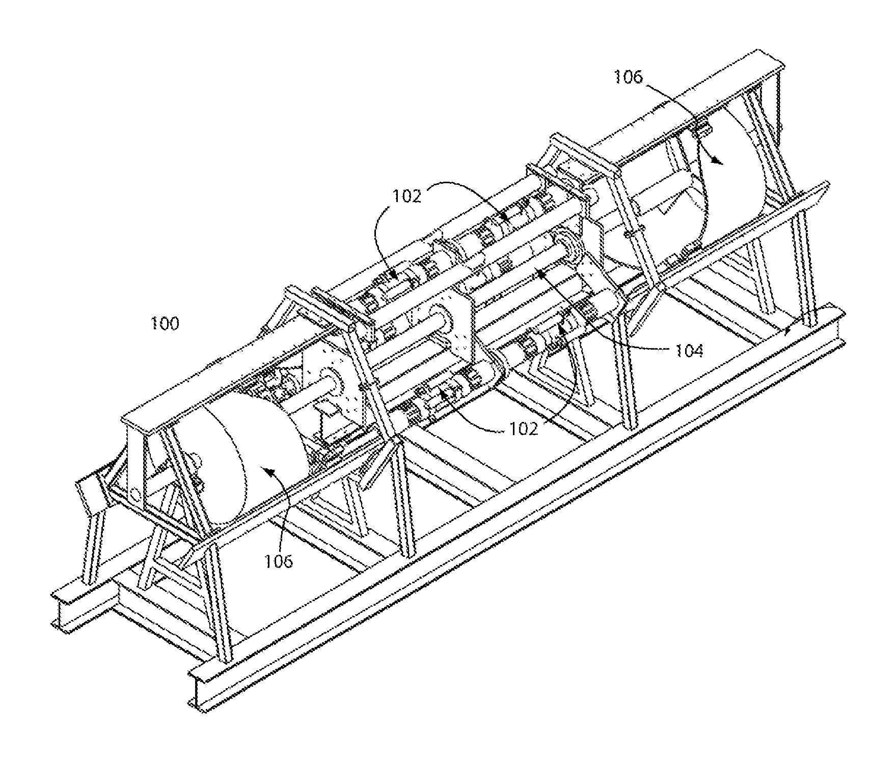
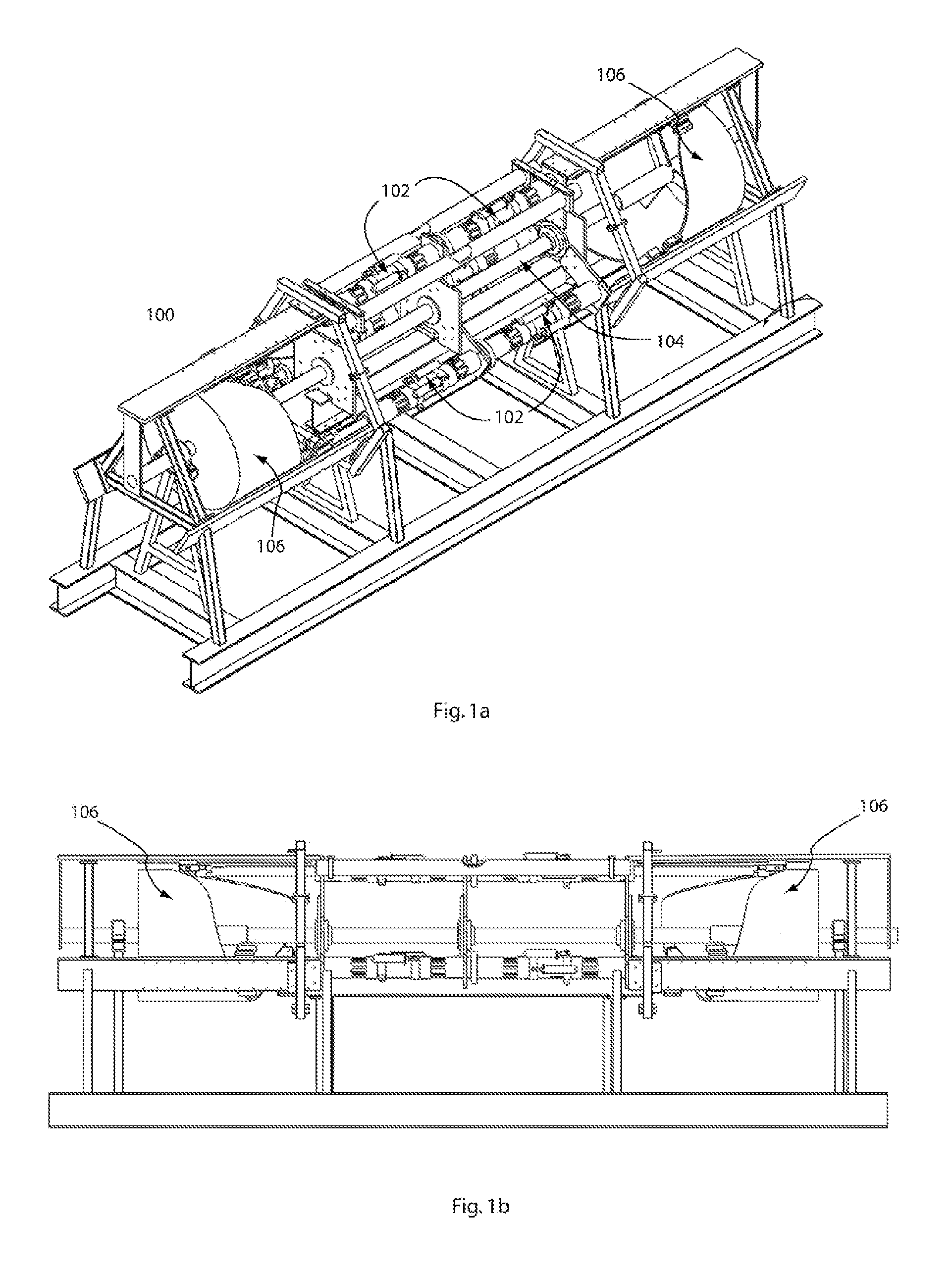
[0037]FIGS. 1-4 illustrate the details of the preferred embodiment of the engine. FIG. 1a shows an isometric view of the inventive engine 100, showing all mechanical components and supporting superstructure. The radial symmetry of engine 100 is also evident. For simplicity, only three cylinders 102 of a plurality of cylinders are shown disposed in the central portion of engine 100, and coaxially oriented with central shaft 104 and positioned at 120° intervals around central shaft 104. The dual rotary end cams 106 are shown mounted at each end of central shaft 104. Each of the cylinders 102 contains a pair of opposed pistons (not visible) that are coupled to the end cams 106 at each end through piston rods.

[0038]FIG. 1b shows a frontal view of the same engine 100, showing the bilateral symmetry of the dual-cam engine. Each cam 106 is a mirror image of the other, whereby their cam profiles are aligned in opposition so that the pistons act in phase duri...


PUM


Abstract

A high thermal efficiency reciprocating hydrogen-fueled engine for ultra-high altitude long endurance flight and its method of operation are described. The engine is based on an opposed piston barrel design where long cylinders are employed to accommodate extraordinarily large compression and expansion strokes where the corresponding ratios are over 50:1, taking advantage of the very low ambient air pressures and temperatures at 60,000 ft and higher to reduce the overall weight and strength requirements of the inventive engine that would be a factor for operation at lower altitudes. The engine is designed to obtain more than 70% indicated thermal efficiency when operated at ultra-high altitudes of 60,000 ft and greater. A combination of large compression ratios combustion temperature optimization and management, instantaneous and complete combustion at TDC, followed by a rapid and long expansion stroke using tailored control of piston movement provide the means to achieve such high efficiencies.

Description

PRIORITY CLAIM[0001]This application claims priority to U.S. Provisional Patent Application No. 61 / 532,062 filed Sep. 7, 2011.FIELD OF THE INVENTION[0002]The invention relates to highly efficient engines for propeller-driven ultra-high altitude and stratospheric fixed-wing flight.BACKGROUND OF THE INVENTION[0003]Improvements in jet engine technology over the last half-century have steadily led to a 55% increase in engine fuel efficiency per seat-kilometer since the introduction in the late 1950s of the Boeing 707 aircraft. With the advent of the high bypass turbofan engine, now ubiquitous in civil jet aviation, the fuel consumption per seat-kilometer is about equal to that of early commercial piston-prop airliner engines (data from National Aerospace Laboratory (The Netherlands) report NLR-CR-2005-669). Nevertheless, the low thermal efficiency of these engines (30%-40%) is not sufficient to compensate the rising cost of jet fuel. Low fuel efficiencies require commercial airliners to...

Claims


Application Information

Patent Timeline
IPC IPC(8): F02B75/28F02B47/02
CPCY02T10/32F02B75/282F02B43/10Y02T10/30
Inventor SNELL, WILLIAM
Owner SNELL WILLIAM
Why Eureka
Try Eureka