Supercharge Your Innovation With Domain-Expert AI Agents!

System and method for zero reaction time combustion

a technology of reaction time combustion and system, applied in the direction of combustion types, intermittent jet plants, lighting and heating apparatus, etc., can solve the problem of low resistance to gas flow

Inactive Publication Date: 2013-08-22
SOUNDBLAST TECH
View PDF12 Cites 0 Cited by
  • Summary
  • Abstract
  • Description
  • Claims
  • Application Information

AI Technical Summary

Benefits of technology

The present invention is an improved system and method for ignition of a gaseous or dispersive fuel-oxidant mixture. The device includes a tube with an ignition point and an open end, and an igniter placed at the ignition point. The gaseous or dispersive fuel-oxidant mixture flows through the tube and the igniter continuously ignites it, resulting in a zero reaction time combustion that produces exhaust and a continuous pressure. The exhaust travels from the ignition point to the open end of the tube. The system may also include a valve located inside the tube and a control mechanism for controlling the zero reaction time combustion. The technical effects of the invention include improved ignition efficiency, reduced emissions, and improved thrust control.

Problems solved by technology

For example, one embodiment uses ¼″ diameter tubing to prevent such flashback and yet presents a low resistance to gas flow.

Method used


Image

  • System and method for zero reaction time combustion
  • System and method for zero reaction time combustion
  • System and method for zero reaction time combustion

Examples


Embodiment Construction

[0040]The present invention will now be described more fully in detail with reference to the accompanying drawings, in which the exemplary embodiments of the invention are shown. This invention should not, however, be construed as limited to the embodiments set forth herein; rather, they are provided so that this disclosure will be thorough and complete and will fully convey the scope of the invention to those skilled in the art. Like numbers refer to like elements throughout.

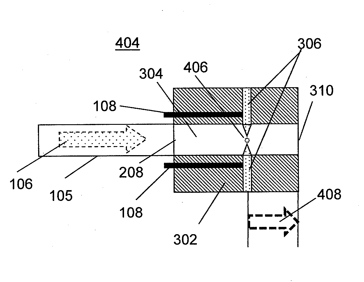
[0041]The present invention is a system and method for zero reaction time combustion where continuous ignition of a gaseous or dispersive fuel-oxidant mixture flowing within a tubular structure generates a constant pressure or thrust. The zero reaction time combustion process involves continuously igniting a flowing (or moving) stream of gas and oxidizer mixture that is filling a tube. To initiate the process, a desired ratio and flow rate of the flowing stream of gas and oxidizer mixture is supplied to the tub...


PUM


Abstract

A system and method for zero reaction time combustion is provided where a gaseous or dispersive fuel-oxidant mixture is supplied to a fill point of a tube having a fill point and an open end. An igniter placed at an ignition point in the tube continuously ignites the gaseous or dispersive fuel-oxidant mixture while the gaseous or dispersive fuel-oxidant mixture is flowing through the tube thereby continuously producing zero reaction time combustion at that ignition point that produces exhaust and a continuous pressure. The exhaust travels from the ignition point to the open end of the tube.

Description

FIELD OF THE INVENTION[0001]The present invention relates generally to a system and method for zero reaction time combustion. More particularly, the present invention relates to a system and method for zero reaction time combustion where continuous ignition of a gaseous or dispersive fuel-oxidant mixture flowing within a tubular structure generates a constant pressure or thrust.BACKGROUND OF THE INVENTION[0002]Many prior art gas detonation systems are based on a deflagration to detonation transition (DDT) process that requires long tubes or highly detonable gas mixtures such as oxygen and hydrogen in order to produce a detonation. Otherwise such systems would only deflagrate which is a slow and nearly silent process. FIG. 1A depicts a side view of a prior art DDT system. A detonation tube 100 has separate fuel supply 102 and oxidizer supply 104 which are opened during a fill period to fill detonation tube 100 with fuel-oxidant mixture 106. After the fill period, fuel supply 102 and ...

Claims


Application Information

Patent Timeline
Patent Type & Authority Applications(United States)
IPC IPC(8): F02K9/95F23D14/62F23Q3/00F23D14/38
CPCF23Q13/005F23R7/00F02K9/95F02K7/02F23D14/62F23Q3/008F23D14/38
Inventor FULLERTON, LARRY W.
Owner SOUNDBLAST TECH
Features
  • R&D
  • Intellectual Property
  • Life Sciences
  • Materials
  • Tech Scout
  • Unparalleled Data Quality
  • Higher Quality Content
  • 60% Fewer Hallucinations
Learn More