Heat pipe heat dissipation structure

Active Publication Date: 2013-08-22
ASIA VITAL COMPONENTS SHENZHEN CO LTD
View PDF23 Cites 22 Cited by
  • Summary
  • Abstract
  • Description
  • Claims
  • Application Information

AI Technical Summary

Benefits of technology

[0011]A primary object of the present invention is to provide an improved heat pipe heat dissipation structure, which has better heat transfer efficiency
[0012]A further object of the present invention is to provide the above heat pipe heat dissipation structure, which is able to bear greater thermal power impact per unit area and is able to transfer more amount of heat.
[0013]To achieve the above and other objects, the heat pipe heat dissipation structure of the present invention includes a main body. The main body has an evaporation section, a condensation section outward extending from the ev

Problems solved by technology

However, this leads to another problem.
That is, the capillary structure disposed on the inner wall face of the chamber of the heat pipe is limited.
As a result, the amount of the working fluid absorbed by the capillary structure on the evaporation section is limited.
Therefore, in case that the evaporation section of the heat pipe is used to absorb the heat generated by an electronic component with larger power, the working fluid in the capillary structure on the evaporation section often fails to process t

Method used


Image

  • Heat pipe heat dissipation structure
  • Heat pipe heat dissipation structure
  • Heat pipe heat dissipation structure

Examples


Embodiment Construction

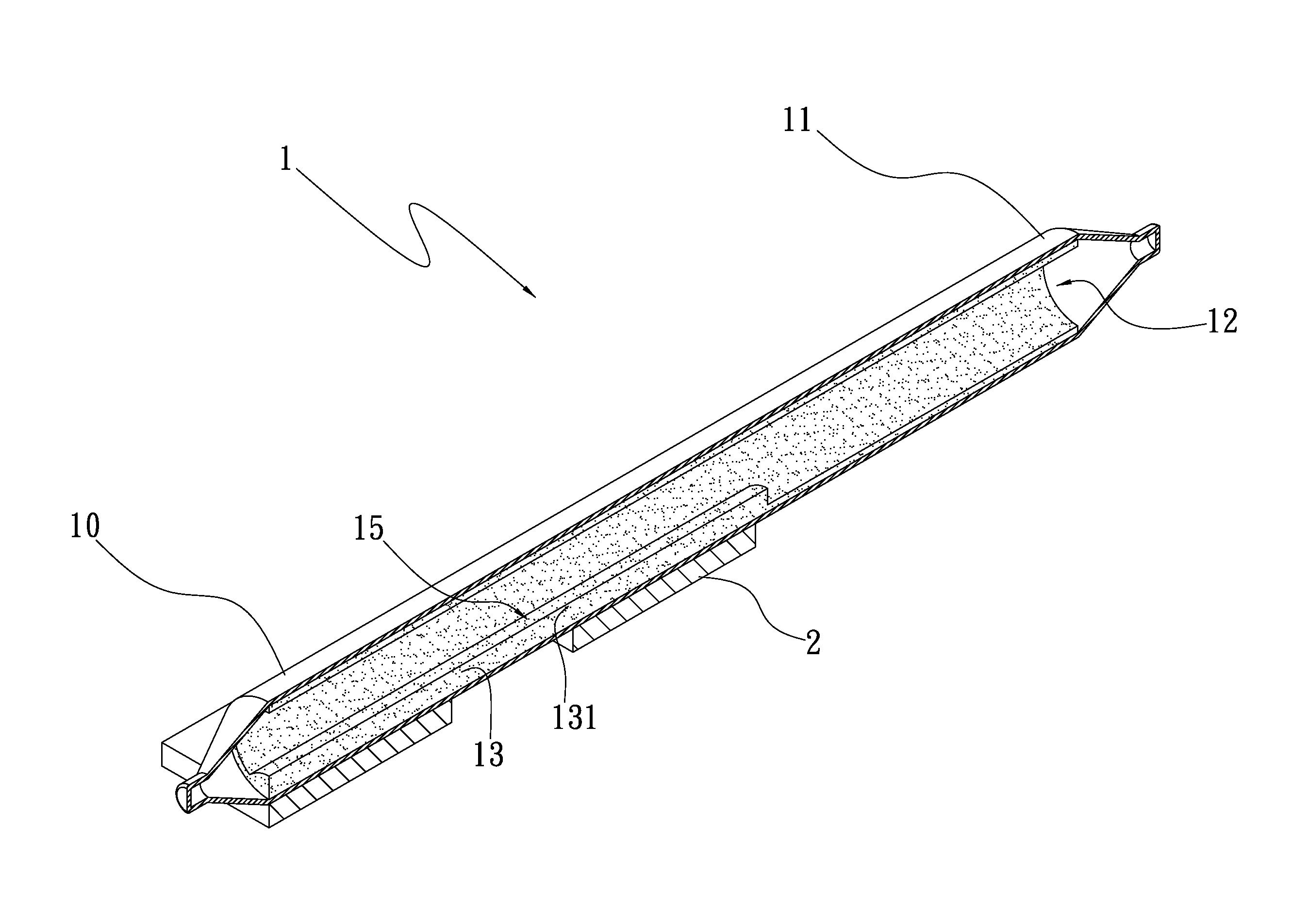
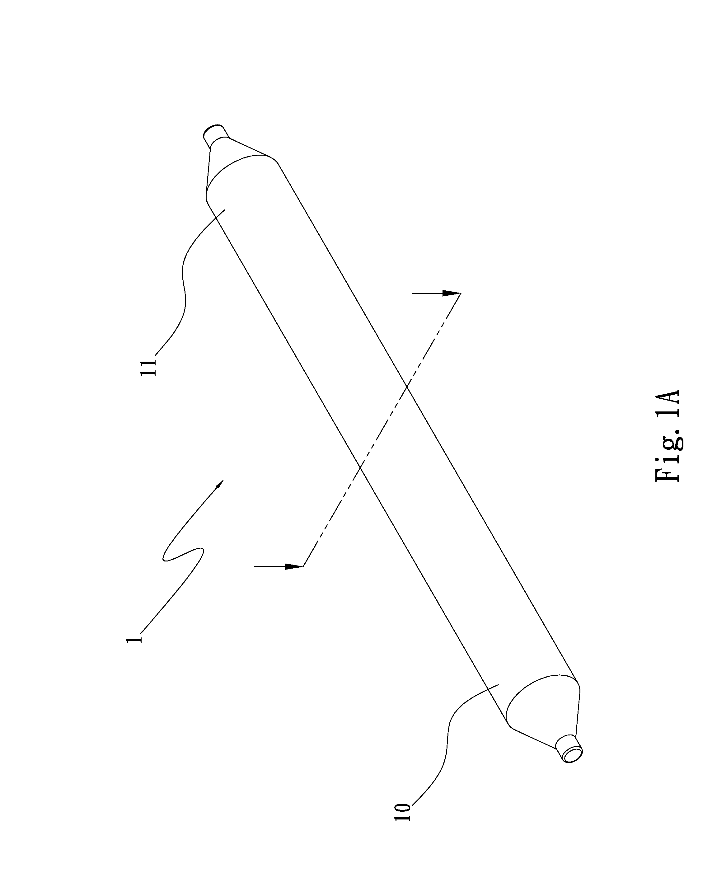
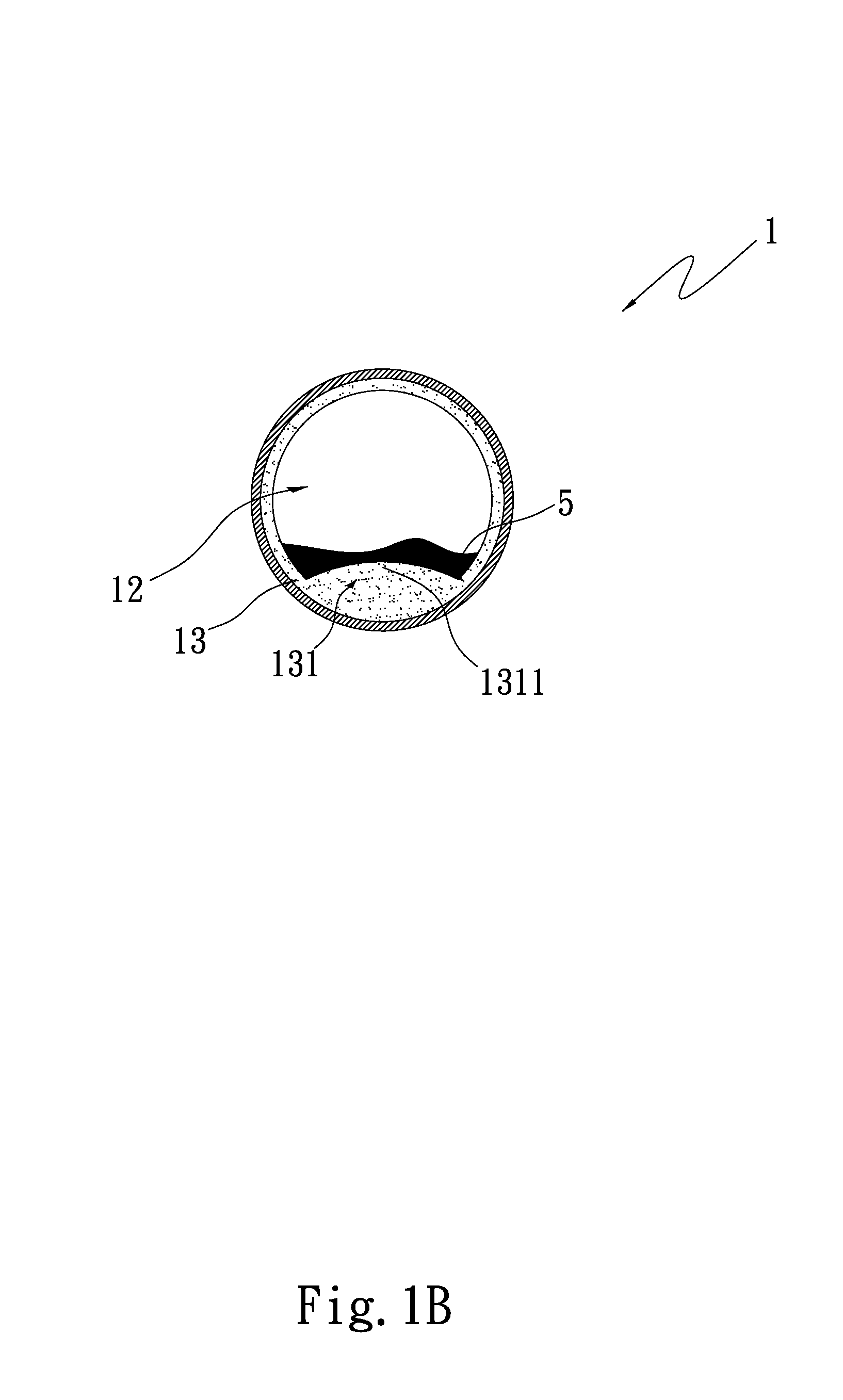
[0024]Please refer to FIGS. 1A and 1B. FIG. 1A is a perspective view of a first embodiment of the heat pipe heat dissipation structure of the present invention. FIG. 1B is a sectional view of the first embodiment of the heat pipe heat dissipation structure of the present invention. According to the first embodiment, the heat pipe heat dissipation structure of the present invention includes a main body 1, which is a heat pipe in the form of a circular tube. The main body 1 has an evaporation section 10, a condensation section 11 outward extending from the evaporation section 10, a chamber 12 and at least one first capillary structure 13. In this embodiment, an inner wall face of the chamber 12 is a smooth wall face for illustration purposes. A working fluid is filled in the chamber 12. The working fluid is selected from a group consisting of pure water, inorganic compound, alcohol, ketone, liquid metal, coolant and organic compound.

[0025]The first capillary structure 13 is disposed o...


PUM


Abstract

A heat pipe heat dissipation structure includes a main body. The main body has an evaporation section, a condensation section, a chamber filled with a working fluid and at least one first capillary structure. The first capillary structure is disposed on an inner wall face of the chamber. The first capillary structure has at least one swelling capillary section. The swelling capillary section swells from a part of the first capillary structure in the evaporation section. The heat pipe heat dissipation structure is able to greatly increase heat transfer efficiency.

Description

BACKGROUND OF THE INVENTION[0001]1. Field of the Invention[0002]The present invention relates generally to a heat pipe heat dissipation structure, and more particularly to an improved heat pipe heat dissipation structure, which has better heat transfer efficiency and is able to bear greater thermal power impact.[0003]2. Description of the Related Art[0004]Recently, following the rapid advance of electronic techniques, various high-frequency and high-speed electronic components have been developed. Also, the integrated circuits have become more and more compact and miniaturized. Therefore, the amount of heat generated by the electronic components per unit capacity is abruptly increased. The conventional heat dissipation measures include radiating fins, heat pipes, heat conduction interfaces, etc. Nowadays, it has become a critical topic how to dissipate the heat generated by the electronic components of the more compact integrated circuit at higher heat dissipation efficiency so as t...

Claims


Application Information

Patent Timeline
IPC IPC(8): F28D15/04
CPCF28D15/046F28D15/0233F28D15/04
Inventor WU, CHUN-MING
Owner ASIA VITAL COMPONENTS SHENZHEN CO LTD
Why Eureka
Try Eureka