Valve Device, Brake System and Vehicle

a valve device and brake system technology, applied in the field of valve devices, can solve the problems of high cost of production of the known valve device, low unit quantity, complex and expensive equipment for different brake systems, etc., and achieve the effect of simple technical configuration, low unit quantity and convenient operation

Active Publication Date: 2013-08-22
ZF CV SYST EURO BV
View PDF18 Cites 31 Cited by
  • Summary
  • Abstract
  • Description
  • Claims
  • Application Information

AI Technical Summary

Benefits of technology

[0027]The housing covers may be of either identical or different design for the valve devices with different housings and / or with different inserts. It may for example be advantageous, despite resulting lower unit quantities in which identical housing covers must be produced, to produce a plurality of different housing covers, because for example the production of a cover for a valve device formed as a relay valve may be less expensive, owing to simpler technical configuration, than the production of additional covers that can also be used for a valve device formed as a modulator.
[0028]The insert is preferably surrounded by the housing block and by the housing cover and clamped to the housing. In this way, it is possible, for example, for the cover to be screwed to the housing block so as to surround the insert, such that when the housing cover is screwed on, pneumatic connections are simultaneously produced between the housing and the insert, and the insert is fixedly fastened to the housing. An exchange of the insert, for example for the repair of the valve device in the event of a defect in the insert, can thus be performed easily by simply unscrewing the cover, exchanging the insert and subsequently screwing the cover onto the housing block again. The cover is a replacement part that can be repaired in a workshop.

Problems solved by technology

This makes it complex and expensive to equip vehicles with different brake systems.
Furthermore, it is necessary to produce a multiplicity of different housings, which leads to low unit quantities and consequently high costs of production of the known valve devices.
In the known valve devices, it is necessary, in a cumbersome manner, for plug elements to be positioned precisely and such that they remain permanently in position.
An intended mode of operation of the respective valve device, such as is desired or necessary in the case of the abovementioned valve devices for utility vehicles, would otherwise be impaired.
It would therefore appear to be disadvantageous for an air guide or pressure medium guide which can be varied by means of plug elements to be provided in the case of the abovementioned valve devices with relay valve.

Method used


Image

  • Valve Device, Brake System and Vehicle
  • Valve Device, Brake System and Vehicle
  • Valve Device, Brake System and Vehicle

Examples


Embodiment Construction

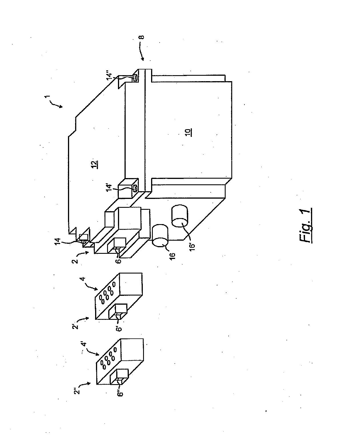
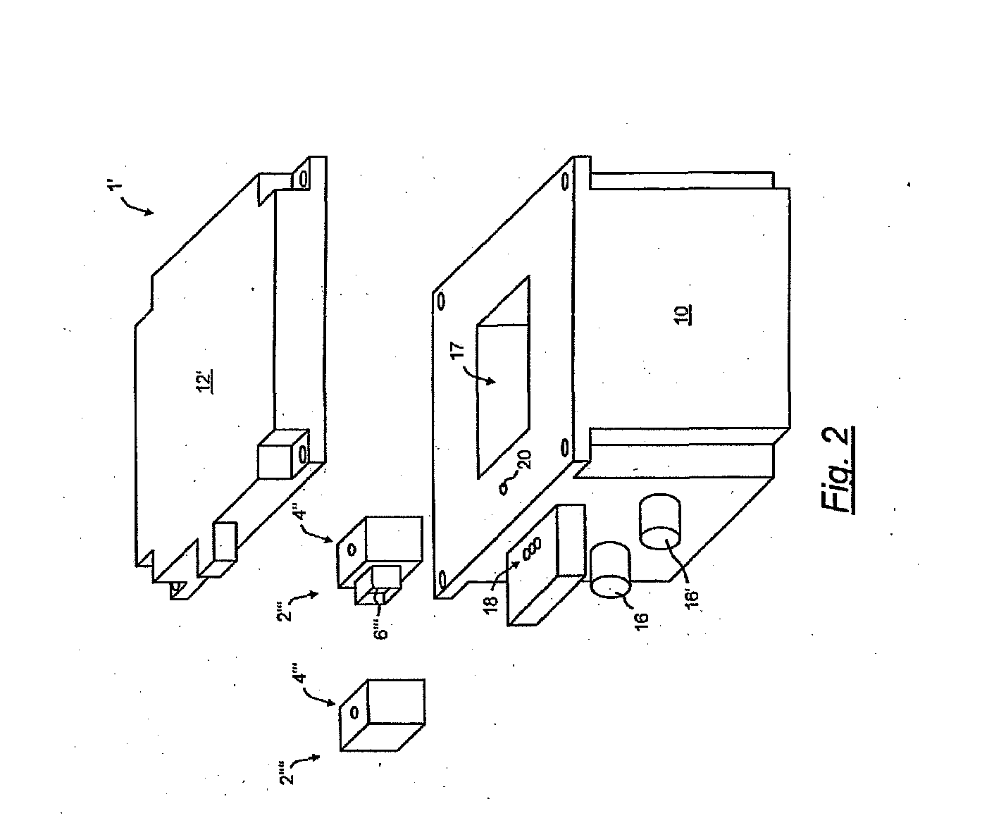
[0049]FIG. 1 shows a valve device 1 for a compressed-air-operated brake system of a utility vehicle. Brakes of the vehicle can be actuated by means of the valve device 1. The valve device 1 has an insert 2 formed as a valve block. Owing to the selected insert 2, the valve device 1 is a relay modulator device for an electronically regulated brake system. With alternatively selectable inserts 2′ and 2″, which are likewise formed as valve blocks, the valve device 1 would, by contrast, be a relay modulator device for a pneumatic brake system or a relay modulator device for an electropneumatic parking brake. Here, the inserts 2, 2′ and 2″ are externally of identical design, or are of identical external appearance, but have different air guides and / or different valves in the interior. Internal pneumatic ports 4 of the insert 2′ are however identical to internal pneumatic ports 4′ of the insert 2″ and to internal pneumatic ports (not shown) of the insert 2. Furthermore, the inserts 2, 2′ a...


PUM


Abstract

A valve device for brake control of a different pressure medium-operated vehicle brake systems comprises a housing that has pressure medium ducts. A relay valve provides a pneumatic control pressure, which is fed to the relay valve via at least one of the pressure medium ducts at a higher flow rate. At least one insert is pneumatically connected to at least two of the pressure medium ducts, which can be pneumatically connected to each other by the insert. The two pressure medium ducts define a pressure medium path, the profile of which differs based on the housing that is in each case selected and/or switched based on the selected insert. The housing is selected from a set of housings having different pressure medium ducts, in particular bores, but which are otherwise essentially similar. The insert is selected from a set of different inserts.

Description

FIELD OF THE INVENTION[0001]The present invention generally relates to a valve device for brake control of a pressure-medium-operated brake system of a vehicle.BACKGROUND OF THE INVENTION[0002]Pressure-medium-operated brake systems are used in particular for utility vehicles. Here, compressed air is preferably used as the pressure medium. For the actuation of a service brake of the vehicle or for the release of a parking brake of the vehicle, a control pressure is modulated by electropneumatic and / or pneumatic means and is provided at a boosted air flow rate, or at a higher pressure medium flow rate, by means of a relay valve. Here, the relay valve is part of the valve device and is preferably arranged in a housing of the valve device.[0003]From the relay valve, the pressure medium with boosted pressure medium flow rate is conducted to at least one brake cylinder in order to brake at least one wheel of the vehicle or is conducted to a spring store part of a combined spring brake cyl...

Claims


Application Information

Patent Timeline
Patent Type & Authority Applications(United States)
IPC IPC(8): B60T13/68F16K31/02
CPCB60T13/683B60T15/00F16K31/02B60T13/68B60T17/04Y10T137/86574
Inventor KIEL, BERND-JOACHIMROSENDAHL, HARTMUTROTERS, GERDSTRACHE, WOLFGANGSTRUWE, OTMAR
Owner ZF CV SYST EURO BV
Why Eureka
Try Eureka